Sign In
Upload
Download
Table of Contents
Contents
Add to my manuals
Delete from my manuals
Share
URL of this page:
HTML Link:
Bookmark this page
Add
Manual will be automatically added to "My Manuals"
Print this page
×
Bookmark added
×
Added to my manuals
Manuals
Brands
Mindray Manuals
Indoor Furnishing
HyBase 8300
Operator's manual
Mindray HyBase 8300 Operator's Manual
Operating table
Hide thumbs
1
2
3
4
5
6
Table Of Contents
7
8
9
10
11
12
13
14
15
16
17
18
19
20
21
22
23
24
25
26
27
28
29
30
31
32
33
34
35
36
37
38
39
40
41
42
43
44
45
46
47
48
49
50
51
52
53
54
55
56
57
58
59
60
61
62
63
64
65
66
67
68
69
70
71
72
73
74
75
76
77
78
79
80
81
82
83
84
85
86
87
88
89
90
91
92
93
94
95
96
97
98
99
100
101
102
103
104
105
106
107
108
109
110
111
112
113
114
115
116
117
118
119
120
121
122
123
124
125
126
127
128
129
130
131
132
133
134
135
136
137
138
139
140
141
142
143
144
145
146
147
148
149
150
151
152
153
154
155
156
157
158
159
160
161
162
163
164
165
166
167
168
169
170
171
172
173
174
175
176
page
of
176
Go
/
176
Contents
Table of Contents
Troubleshooting
Bookmarks
Table of Contents
Table of Contents
1 System Overview
Main Components
Definitions
Graphical Symbols
Safety Notes
Definition of Slope/Tilt/Slide
Definition of Permissible Overall Load
Definition of Central Position
Definition of 0 Position
Definition of Standard Range and Extended Range of the Longitudinal Slide
Definition of Sound Signals
Warning Label
Central Position
Height for Operating Table Locking Mechanism with an Overall Load of up to 135 Kg
Protection Label
Sitting Label
Consulting Accompanying Documents Label
Intended Use
Fundamental Safety Instructions
Instructions against Personal Injury
Instructions against Property Damage
2 Daily Operations
Power Supply Systems
AC Power
Battery
Potential Equalization
Setting up Potential Equalization
Control Units
General
Override Panel
Corded Hand Control (Optional)
Corded Hand Control with LCD (Optional)
IR Remote Control with LCD (Optional)
Foot Switch (Optional)
Patient Orientation
Definition of Patient Orientation
Setting the Patient Orientation
Mechanical Adjustments
Dual-Joint Head Plate (Optional)
Extension Plate (Optional)
Dual-Joint Leg Plate (Optional)
Head Plate (Optional)
Upper Back Plate (Optional)
Leg Plate (Optional)
Foam Pad
Table Pad
3 Patient Positioning
General
Patient Positioning at an Overall Load between 135Kg and 230Kg
General
Patient Positioning with an Overall Load of up to 135 Kg
General
4 Cleaning and Disinfection
Recommended Cleaning Agents and Disinfectants
Forbidden Cleaning Agents and Disinfectants
Cleaning
Preparations
Cleaning Procedure
Disinfection
General
Disinfection Procedure
Cleaning
Table Pad
Disinfection
Swivel Castor
5 Maintenance
Inspections and Maintenance
Inspections
6 Troubleshooting
Malfunctions and Troubleshooting
Extending the Castors in Emergency
7 Clamp
Intended Use
Heavy Radial Clamp
Specifications
Components
Installation and Use
Light Radial Clamp
Specifications
Components
Installation and Use
Heavy Square Clamp
Specifications
Components
Installation and Use
Light Square Clamp
Specifications
Components
Installation and Use
Cleaning and Disinfection
Cleaning
Disinfection
8 Anesthesia Frame
Intended Use
Heavy Anesthesia Frame
Specifications
Components
Installation and Use
Light Anesthesia Frame
Specifications
Components
Installation and Use
U-Shaped Anesthesia Frame
Specifications
Components
Installation and Use
Cleaning and Disinfection
Cleaning
Disinfection
9 Arm Board
Intended Use
Heavy Arm Board
Specifications
Components
Installation and Use
Light Arm Board
Specifications
Components
Installation and Use
Cleaning and Disinfection
Cleaning
Disinfection
Cleaning/Disinfecting Pad
Cleaning Fastening Strap
10 Appendices
A Technical Specifications
Classification
Environment
Load
Specifications
Accessories
Emc
B Index
Advertisement
Quick Links
1
Main Components
2
Inspections and Maintenance
3
Malfunctions and Troubleshooting
4
A Technical Specifications
Download this manual
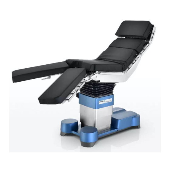
Operator's Manual
HyBase 8300/HyBase 8500
Operating Table
Table of
Contents
Previous
Page
Next
Page
1
2
3
4
5
Advertisement
Table of Contents
Need help?
Do you have a question about the HyBase 8300 and is the answer not in the manual?
Ask a question
Questions and answers
Related Manuals for Mindray HyBase 8300
Indoor Furnishing Mindray HyBase 8500 Operator's Manual
Operating table (176 pages)
This manual is also suitable for:
Hybase 8500
Table of Contents
Save PDF
Print
Rename the bookmark
Delete bookmark?
Delete from my manuals?
Login
Sign In
OR
Sign in with Facebook
Sign in with Google
Upload manual
Upload from disk
Upload from URL


Need help?
Do you have a question about the HyBase 8300 and is the answer not in the manual?
Questions and answers