
Related Manuals for COURSEMASTER CM800i

Summary of Contents for COURSEMASTER CM800i
- Page 1 COURSEMASTER AUTOPILOTS Australia's world leader in autopilot technology CM800 SYSTEM MANUAL 02-09...
- Page 2 CM800 SYSTEM MANUAL Your Coursemaster CM800i autopilot system is engineered for accurate and reliable steering. But remember that it cannot keep a lookout. SAFE NAVIGATION IS ALWAYS YOUR RESPONSIBILITY. COURSEMASTER AUTOPILOTS PTY LTD. 2/66 LOWER GIBBES STREET, CHATSWOOD NSW. AUSTRALIA 2067...
- Page 3 THE CM800 SYSTEM The ‘intelligent’ CM800 autopilot system may use CM800i or CM850i controllers in combination with a CM840 or CM841 Junction Box. This manual describes the use of each configuration and some details may therefore not apply to your particular system. It is possible also to upgrade an earlier CM800 system to the latest version simply by fitting a new software chip.
- Page 4 QUICK START • Install and check the system as described in Chapter 3. • Press the STANDBY key to turn the system on. • Follow the on-screen instructions to carry out the initial setup • Press the STANDBY and PILOT keys together to turn off. •...
-
Page 5: Table Of Contents
1.1 Introduction to autopilots 1.1.1 The Reference Course 1.1.2 Steering Control 1.1.3 Power Steering 1.1.4 Options 1.1.5 Working with other Equipment 1.2 The CM800i System 1.3 Optional attachments OPERATING INSTRUCTIONS 2.1 The Control Panel 2.2 Getting Started 2.2 Normal Operation... - Page 6 CONTENTS INSTALLATION Step-by-step Summary 3.1 Junction Box 3.2 Controller 3.3 Compass options 3.4 Rudder Transducer 3.5 Attachments 3.5.1 Remote Steering 3.5.2 Rate Gyro 3.5.3 Second Controller 3.5.4 Rudder Angle Indicator 3-10 3.5.5 Remote Alarm 3-10 3.5.6 NMEA Interfaces 3-10 3.6 Steering Drive 3-11 3.6.1 Chain driven mechanical 3-12...
-
Page 7: System Description
The four basic components of an autopilot are a compass, an electronic control box, a rudder angle sensor (transducer) and the steering drive. See Fig 1.1. In a CM800i system, the electronics are housed in two cases - a Junction Box containing most of the system and a Controller (Control Head), which is mounted near the steering station. -
Page 8: The Reference Course
Automatic Tuning In an auto-tuning autopilot, such as the CM800i system, this choice of the appropriate rudder correction is made automatically. The autopilot uses data about the type of vessel, which is entered during the set-up operation. - Page 9 System Description 1-3 Rudder Factor (Manual) The sensitivity or RUDDER FACTOR sets how many degrees of helm are applied for a given course error. A mid-range rudder factor setting applies half a degree of helm for each degree off course. In large or slow vessels it would be more and in light, fast boats it may be less.
-
Page 10: Power Steering
System Description 1-4 The action of the rate or counter-rudder during a turn is illustrated in Fig 1.3. Generally, when the rate component is increased, vessels hold a course better but react to changes in the reference course more slowly. Counter-rudder also improves control for most vessels operating in a following sea. -
Page 11: Working With Other Equipment
Conversely, it has also been engineered to operate without causing interference to radio receivers and other communications equipment. Coursemaster autopilots carry a CE mark to indicate compliance with the relevant EMC standards. The installation sections of this manual have been carefully developed to minimise problems when the autopilot is in this environment. -
Page 12: The Cm800I System
System Description 1-6 1.2 THE CM800i SYSTEM The core of the CM800i system is built by connecting a Controller to a Junction Box. There is a choice between two versions of the Controller and two versions of the Junction Box. A comparison of their features between is shown in Fig 1.4 below. - Page 13 System Description 1-7 The shape of the final system is determined by the optional attachments and many combinations may be set up. Figs 1.5 shows a full system based on either the CM840 or CM841 Junction Box. The core system components are shown with shading. NMEA 12/24 V NAVIGATION...
-
Page 14: Optional Attachments
Steering Drive There are many mechanical or hydraulic steering options. A suitable drive may either by supplied by Coursemaster or the autopilot may be connected to an existing steering drive on the vessel. 1.3 OPTIONAL ATTACHMENTS... - Page 15 System Description 1-9 Compass Slave If desired, the CM437 or 427 compass may be replaced by a CM428 compass slave mounted above the ship’s card compass. Remote Steering A number of remote steering options are available. The CM654 is a hand-held unit with a cable and the CM655 is a panel-mount version of the CM654.
-
Page 16: Operating Instructions
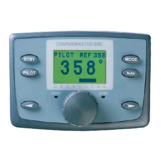
The front panels of the two Controllers (Figs 2.1 and 2.2) contain a text and graphics display, and course error lamps keys. The CM850i also has a course adjust knob, while the CM800i has an ‘on course’ indicator. The use of the controls is described in this chapter. -
Page 17: Getting Started
Operating Instructions _______________________________________________________________ System status Heading Rudder angle Switch on COURSEMASTER 850 Cancel pilot Select display STBY REF 123 Cancel alarms STBY MODE Switch off PILOT Auto navigate Engage Pilot PORT STBD Wind vane Dodge set Auto tack Cancel alarms... - Page 18 Operating Instructions _______________________________________________________________ The next two prompts enter a description of the vessel type, so that the auto-tuning program starts with values that are best suited for it. The Hull Type is set either to Displacement or Planing. Displacement hulls sit level in the water over their range of operating speeds.
- Page 19 Operating Instructions _______________________________________________________________ 29 LIMITS 28 CENTRE HELM PRESS > 02 S The top line shows the stored values of the port and starboard rudder limits. Check that these are close to what you expect and are balanced within 5 degrees. Bring the helm to the position which your experience shows to be centred - the indicated angle may now be different from zero.
-
Page 20: Normal Operation
Operating Instructions _______________________________________________________________ 2.3 NORMAL OPERATION Press the STANDBY key. The system does a self-test for a few Switching seconds and displays the version of software fitted to your autopilot. When the self-test is complete the normal STANDBY display appears and shows the current heading of the vessel. STBY STBY REF 123... -
Page 21: Adjusting The Course
Operating Instructions _______________________________________________________________ CM800i Controller To adjust the current reference course, press either the left or right Adjusting arrow key. A single press changes the course by 1 degree. Holding Course a key down changes the course continuously in 10 degree steps. -
Page 22: Auto Navigation
Operating Instructions _______________________________________________________________ autotack during countdown, press STANDBY or PILOT. As with the course change function, autotack will not work when in the auto-navigate mode. If operating with a wind instrument input, the operation is slightly different. The top line of the display shows ‘W V’ in place of the turn angle and when it turns the new heading sets up the same relative wind angle on the opposite side of the vessel. -
Page 23: Remote Steering
The system is returned to PILOT by pressing the PILOT key. The CM800i system responds to the most recent input from either the control panel or a remote attachment. Therefore, when the system is turned on, the setting of all remotes is ignored until some input is made to them. -
Page 24: The Mode Key
Operating Instructions _______________________________________________________________ The vessel now holds a fixed relative heading to the wind, being the one existing when the NAV or PILOT key was pressed. The relative heading may be adjusted via the course knob or by returning to STANDBY and hand steering the vessel to a new course. -
Page 25: Rudder Factor
Operating Instructions 2-10 _______________________________________________________________ NORMAL Direct proportional control with a counter-rudder component that be adjusted from the menu (see below). More information on manual settings is given in Sec 2.7. ROUGH This suits most vessels in heavy conditions. The control has a deadband which permits a 5 deg yaw about the reference course before correction is applied. -
Page 26: Program Menus
Operating Instructions 2-11 _______________________________________________________________ 2.5 PROGRAM MENUS Three program menus give access to a number of system settings which may be used to fine-tune the performance and select various options. Adjusted settings are stored in permanent memory and are retained while the system is turned off. Hold the MODE down for 2 - 3 seconds and the screen will show: MENU 1 MODE... - Page 27 Operating Instructions 2-12 _______________________________________________________________ Menu 1 BACKLIGHT The backlight for the display can be set to 4 different brightness levels. Use the arrow keys to adjust. RATE GYRO If a CM437 is fitted or a CM626 rate gyro has been fitted as an optional attachment, the gyro function is turned on or off via the arrow keys.
- Page 28 Operating Instructions 2-13 _______________________________________________________________ With the vessel under way and steering it by hand, turn it slowly through a full circle. You may turn either to port or starboard, but the same direction should be maintained until the circle is complete.
- Page 29 Operating Instructions 2-14 _______________________________________________________________ HEADING 225 Turn the vessel to a heading which is close to one of the cardinal or inter-cardinal points, ie. 000, 045, 090, 135, 180, 225, 270, or 315. Then use the arrow keys to adjust the deviation up or down until the heading agrees with that of the ship's compass or other reference compass.
- Page 30 Operating Instructions 2-15 _______________________________________________________________ COLD START PRESS STANDBY MENU 2 RUDDER LIMITS This setting controls the maximum rudder angle used when the system is in PILOT mode. It is preset to 20 degrees and may be changed using the arrow keys. It should always be less than the mechanical limits stored during the System Setup procedure.
- Page 31 Operating Instructions 2-16 _______________________________________________________________ ADJUST A magnetic variation value must be entered if GPS sentences VARIATION containing TRUE headings are used. The variation is displayed on a 360 degree scale, i.e. 13 degrees east appears as 013, while 10 degrees west appears as 350. Use the COURSE keys to adjust the variation.
-
Page 32: Alarms
1 and 4. 2.6 ALARMS The CM800i System has a number of alarm functions. When an alarm occurs, the beeper sounds and an alarm message appears on the display. To cancel an alarm, press the STANDBY or PILOT key. If the system is in PILOT and this key is used to cancel an off-course alarm, for example, the reference course is not changed. -
Page 33: Recommended Settings
Operating Instructions 2-18 _______________________________________________________________ COMPASS FAULT If a fluxgate compass has been selected, the magnetic field being sensed by the compass is above or below preset limits. Further information is given in Chap. 4. NO HEADING DATA If a digital heading input has been selected, a valid heading sentence is not being received. - Page 34 Operating Instructions 2-19 _______________________________________________________________ and slow down the completion of a course change. Setting it too low produces over- shooting during course change.
-
Page 35: Installation
CHAPTER 3 INSTALLATION Before proceeding with the installation, check the contents of the shipment to ensure that all components ordered are present and undamaged. If a steering motor or hydraulic drive is included, check that its voltage rating is suitable for the vessel's supply. -
Page 36: Junction Box
Installation _________________________________________________________________________ 6. Install the steering drive as described in Sect 3.6 7. Apply power to the Junction Box. Now turn to Section 2.2 of this Manual - Getting Started - and carry out the initial setup. 3.1 JUNCTION BOX The Junction Box should mounted on a vertical surface with the cable entry holes facing downwards. - Page 37 Installation _________________________________________________________________________ RELAY MICROPROCESSOR PROGRAM STORE RELAY 0A FUSE 0.8A FUSE NMEA PORT A/B REMOTE 2 CONTROL 2 POWER MOTOR/CL RUDDER MTR ALM REMOTE 1 CONTROL 1 COMPASS/GYRO Figure 3.2 Layout of CM 841 Junction Box components and connectors. Note: The fluxgate/slave selector switches are fitted to suit an earlier model of compass slave (CM418).
-
Page 38: Controller
Installation _________________________________________________________________________ 3.2 CONTROLLER The Controller may be mounted in any convenient position. Although the front of the controller is weather-proofed, it should not be mounted where it is exposed directly to rain or spray. The cable plug and socket at the rear of the case are not weather- proofed. - Page 39 Installation _________________________________________________________________________ 3.3 COMPASS The performance of the compass affects the performance of the whole system and some care should be taken in locating it in the best position. If a compass slave, mounted on the glass face of the ship’s flat top compass, is being used, performance is mainly dictated by the accuracy of the ship’s compass.
- Page 40 Installation _________________________________________________________________________ COMPASS SCREEN SCREEN SCREEN SCREEN BROWN BROWN BLUE BLUE CM437 SCREEN CM437 WHITE WHITE CABLE CABLE YELLOW BLUE YELLOW BLUE GREEN WHITE GREEN WHITE YELLOW BROWN YELLOW SCREEN GREEN GREEN IN + IN – ORANGE BROWN GREEN GYRO/PORT B Figure 3.4.
-
Page 41: Rudder Transducer
Installation _________________________________________________________________________ Steel Vessels Steel hulls distort the natural pattern of the earth's magnetic field. In many cases these deviations can be adjusted out through the calibration procedures. In others, a strong vertical field component may exist which will prevent the compass giving good performance. -
Page 42: Attachments
Installation _________________________________________________________________________ RUDDER TRANSDUCER TILLER OR QUADRANT LINK ROD Figure 3.6 Rudder Transducer Linkage Lay the cable back to the Junction Box and terminate it in the Rudder Transducer plug as shown in Fig 3.7. SCREEN SCREEN ALARM METER RUDDER ORANGE ORANGE TRANSDUCER... -
Page 43: Rate Gyro
Figure 3.9 Rate Gyro connection. 3.5.3 SECOND CONTROLLER A second Controller, which is either a CM800i or CM850i unit, is mounted as for the first Controller. In a CM840 Junction Box, it connected in parallel to the first Controller cable. -
Page 44: Rudder Angle Indicator
Installation 3-10 _________________________________________________________________________ 3.5.4 RUDDER ANGLE INDICATOR The CM530 and CM630 Rudder Angle indicators are two-wire meters which are connected between the METER and ORANGE terminals of the Rudder Transducer socket in the Junction Box. The polarity of the connection may be changed to obtain the correct direction of indication. -
Page 45: Steering Drive
For existing hydraulic systems using a helm pump, instructions are given below for adding a Coursemaster/Hydrive pump motor. But for systems supplied by other manufacturers, installers should consult the data supplied by the manufacturer. -
Page 46: Chain Driven Mechanical
Installation 3-12 _________________________________________________________________________ 3.6.1 CHAIN DRIVEN MECHANICAL STEERING The drive sprocket on the steering motor matches 12.7mm (1/2 inch) British Standard simple chain. The size of the driven sprocket on the steering wheel is chosen to give the recommended helm response time for the length of the hull. The sprocket size is chosen from Table 3.1 or 3.2 below, depending on the voltage. - Page 47 Installation 3-13 _________________________________________________________________________ Mount the drive unit so that its shaft is parallel to the driven shaft and the two sprockets are in line. After fitting the chain and adjusting its tension, there should be 12mm of deflection for each metre length of chain. (1/2" for each 3 ft.) Lay the four- core motor/clutch cable back to the Junction Box and terminate it according to Fig 3.11.
-
Page 48: Solenoid-Controlled Hydraulics
This valve isolates the system into two completely independent sources of steering power and, if required, can be supplied by your Coursemaster dealer. - Page 49 Installation 3-15 _________________________________________________________________________ Two-Line Steering Systems Two-line systems are by far the most common and are manufactured by many companies world-wide. The best known types include Flexatrol, Hydrive, Marol, Morse, Palm Beach, Seastar, Seipem, Servis, Tenfjord, Teleflex, Vetus, Wills Ridley and Wagner.
- Page 50 Installation 3-16 _________________________________________________________________________ Installation Procedure Install the pump according to the hydraulic connection instructions, mounting it close to the tubes connecting the helm pump and cylinder. The pump must be mounted with its rubber foot horizontal. Connect the pump to the system tubing using hose and tubing which is rated for the steering system pressures as specified by the manufacturer.
- Page 51 Installation 3-17 _________________________________________________________________________ After this bleeding operation, leave the reservoir in the helm open and keep it topped up with fluid. Open the bleeder nipple(s) in the slave cylinder. Run the drive pump in one direction by temporarily removing the drive wires and connecting them directly to the battery.
-
Page 52: Hydraulic Linear Drive
_________________________________________________________________________ If the pump runs but does not pump oil, make sure that the system is purged. If that does not succeed, contact your Coursemaster dealer. 3.6.4 HYDRAULIC LINEAR DRIVE Take care, when handling the ram, that the piston rod is not scratched during installation. - Page 53 Installation 3-19 _________________________________________________________________________ amp cable. Connect the two red solenoid wires to the clutch terminals in the Junction Box. (Lighter cable may be used.) Polarity is not important. The cylinder has been bled before shipping. Check the oil level in the pump and, if necessary, top up with automatic transmission fluid.
-
Page 54: Trouble-Shooting
4.2 ERROR MESSAGES The CM800i system is programmed to provide a number of messages on its display when a fault occurs. Some of these are warnings arising out of the way the autopilot is being used. - Page 55 Trouble-Shooting ____________________________________________________________________________________ for. By using this as an aid, many problems can be fixed simply by the owner. If the assistance of a Coursemaster agent is required, quoting the error message will expedite repairs. COMPASS FAULT If a fluxgate is being used, the heading signals from the fluxgate are above or below the preset limits.
-
Page 56: Other Faults
The common symptom is that the steering will drive one way and not the other. Other types of damage can cause the main fuse to blow when the system is switched from STANDBY to PILOT. In such cases, the Junction Box should be returned to your dealer or to Coursemaster for repair. -
Page 57: Fuses
Trouble-Shooting ____________________________________________________________________________________ 4.4 FUSES The system has two fuses. The main 20A (CM840) or 30A (CM841) fuse protects the complete system, while a 0.8A miniature fuse (See Figs 3.1 and 3.2) protects the control electronics against supply surges. -
Page 58: System Specifications
CHAPTER 5 SYSTEM SPECIFICATIONS AUTOPILOT CM840 CM841 Supply Voltage Range (nominal) 12 to 14V dc 12 to 26V dc Maximum Supply Voltage Range 10 to 16V dc 10 to 32V dc Supply Current Basic system in STANDBY 0.33A Add for Controller 2 0.15A In Pilot with 20% duty 2.5A... - Page 59 System Specifications ________________________________________________________________ Steering Drive Output for 12V supply 10V at rated load Output for 24V supply 22V at rated load CM800i CM841 Max continuous current 16 A 25 A Max current for 15 sec. Max current for 1 sec.
- Page 60 System Specifications ________________________________________________________________ AUTOMATIC SENTENCE SELECTION For navigation inputs, the system looks for groups of sentences in this order: RMB and RMC RMB and GLL APB and GLL APA and GLL BOD and XTE The search stops on the first complete group. If only one sentence is found from the above combinations, the autopilot operates from the data in that sentence.
-
Page 61: Maintenance And Warranty
Great care has been taken in the selection and sealing of materials in the system to minimise the risk of corrosion. If, however, the controller or any other component is accidentally immersed in water, it should be drained immediately and returned promptly to your Coursemaster agent for cleaning and rectification. - Page 62 ________________________________________________________________ 6.2 INSTALLATION OF NEW SOFTWARE It is recommended that software upgrades be installed by a Coursemaster dealer, but if this is not possible, the following procedure should be followed carefully by the owner. The memory package containing the software for the main circuit board in the Junction Box has a label beginning CM840V..
- Page 63 Coursemaster Autopilots Pty. Ltd. shall not be liable for any expenses or for any direct or consequential damage caused by defects, failure or malfunction of their autopilots or accessories whether a claim is based on a warranty contract, tort or...
Need help?
Do you have a question about the CM800i and is the answer not in the manual?
Questions and answers