Table of Contents
Advertisement
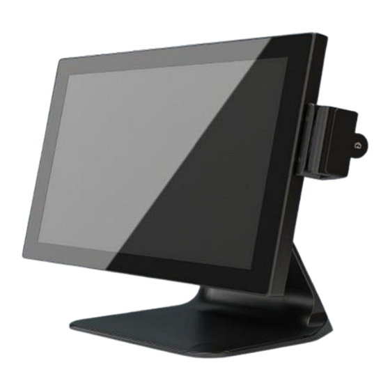
GTA Touch screen EPOS system
operating, installation &
maintenance manual v 1.1
Thank you for choosing Monitor touch screen products, this manual is for GTA-
A8 TC-Touch. Before installing and using the product, please read this manual.
Keep this manual for future use.
This manual contains the latest information as of supply date. We reserve the
right to update or improve the product without notification.
This equipment must be installed by qualified service personnel or distributor.
The company assumes no responsibility for unauthorised changes to the
equipment.
Monitor POS Ltd
8 Church Street, Godalming, Surrey, GU7 1EH
info@monitorpos.co.uk
www.monitorpos.co.uk
email
- 1 -
Advertisement
Table of Contents

Summary of Contents for Monitor POS GTA-A8 TC-Touch
- Page 1 This equipment must be installed by qualified service personnel or distributor. The company assumes no responsibility for unauthorised changes to the equipment. Monitor POS Ltd 8 Church Street, Godalming, Surrey, GU7 1EH info@monitorpos.co.uk www.monitorpos.co.uk...
-
Page 2: Table Of Contents
Table of Contents 1> Safety Precautions ----------------------------------------------------------3 2> Initial installation ----------------------------------------------------------4 3> Taking the Port cover off -------------------------------------------------5 4> Taking the cable tidy trim off --------------------------------------------6 5> Connecting cables into the POS machine ------------------------------7 6> Refitting the coms port cover --------------------------------------------8 7>... -
Page 3: 1> Safety Precautions
Safety Precautions 1、 Choose smooth and vibration-free table to place cash registers; 2、 Cash registers location should ideally be selected away from direct sunlight, with stable temperature, away from water and dust; 3、 Please keep away from strong electromagnetic fields; 4、... -
Page 4: 2> Initial Installation
Initial installation Click here for 1 minute setup video - essential viewing! 1、 Unpacking When you get the machine, immediately unpack and inspect. Report any damage immediately to the transport company and to supplier. After unpacking you should also check whether the contents which should include: CONTENTS Touch screen EPOS system Software and driver CD... -
Page 5: 3> Taking The Port Cover Off
3、 Taking the port cover off for the first time. Undo the two large thumbscrews (medium size flat or crosshead bladed driver recommended) until the back looks as below. Note that the panel is secured at the top edge so you must lift the BOTTOM edge first. Rear panel with two screw fixing securing points Pull up or lever up so that BOTTOM edge opens first - 5 -... - Page 6 4、 Taking the plastic cable tidy trim panel off ** IMPORTANT!!** Early units had a plastic trim which can be stiff to remove and needs a firm pull as shown below. Later units have a magnetic fastening which is much easier to use. Once removed for the first time the process is easier.
- Page 7 5、 Connecting cables into POS machine port area Fit all the cables approximately shown. NOTE: To improve clearance when passing bulky connectors tilt the angle of the screen to make the access hole larger. Coms area showing best angle Max clearance. Larger RS232 serial cables need to be run OUTSIDE if...
- Page 8 Close up showing multiple cables threaded through with strain relief 6、 Refitting the metal coms cover Refitting the top cover is simple, just insert the top edge first, then push in place and refasten the two thumbscrews - 8 -...
- Page 9 7. Fitting the 2 line x 20 character customer display A 2 line x 20 character LCD customer display (VFD optional on request) is available to work with suitably configured EPOS systems. Software settings are: Com Port 2 Character set standard US To Install: Remove the port cover as shown in (3) above and...
- Page 10 If in doubt briefly connect the black cable and power up. Thread the cable through the cover then fix the customer display using the M5 screws supplied Connect the display cable to the small cable which is prewired to com 2 and sits ready in the port area.
- Page 11 8. Fitting the 10.1” TFT screen An integrated 10.1” TFT screen can be fitted to provide customer or marketing information with a correctly configured software system. Here we describe the mechanical and software setup. The screen comes with all cables and a complete replacement port cover for easy fitting.
- Page 12 Software setup of second screen. The display won’t work if you don’t do this! Plug in a mouse and right mouse click on the main desktop. Select Graphics Options > Panel Fit >Monitor > and check the ‘Maintain Display Scaling’ option. Then select Graphics options >...
-
Page 13: 7> Specifications
7、 Specifications Power supply Voltage:220VAC ±15% ±15% Power:45W Frequency:50Hz Working :0℃~40℃ Temperature Storage :-20℃~ +55℃ Relative humidity 20%~90%(40℃) 8、 Preparation before use 1、 Keep cables tidy and routed to avoid strains or stresses. Use the cable tidy system on the unit to have all cables exiting from rear base。 2、... -
Page 14: 9> Pos System Layout
POS Layout 1、15-inch five-wire resistive screen or Multi-point capacitive 2、Power on button 3、2 x USB external 4, Optional 2*20 LCD or VFD customer display 5, Optional MSR +Rfid +Ibutton all in one 6, Optional 10.1 TFT 1280*800 - 14 -... -
Page 15: Product Description
Product Description (1) Description LCD technology parameters; 326mm x 252mm (15.1 inch) Size 304mm x 228mm(4:3) Viewing area Resolution 1024 x 768 Standard Refresh Rate 60Hz Pitch 0.297mm x 0.297mm Colour Response time 16ms (2) Description touch screen technology parameters; Type Five-wire resistive (Capacitive optional) Interface... -
Page 16: Technical Parameters
Technical parameters POS Color Black (optional white for bulk orders) Touch Panel Multi-point capacitive 5-Wire Resistive or LCD Panel 15" TFT 1024*768 64G SSD 2 Interface 1 Interface SATA 2 Interface USB2.0 8 Interface (4 on com panel, 2 external on side, 2 internal on J1900) Power AC 100-240V... - Page 17 (3) MAIN Board connectors Figure(J1900N) - 17 -...
- Page 18 1. Touch panel calibration and setting for resistive screens ( Note that capacitive screens are adjusted through Windows Pen options - 18 -...
- Page 19 This interface can be set to the touch, Beep or No If when you touch the cursor is too far away from your touch point you can use 4 point calibration or for more accuracy 9 point - 19 -...
- Page 20 linearization Touch each X until it stops Press OK after Calibration - 20 -...
-
Page 21: Touch Faq
Touch FAQ Contact with the cursor position does not match Run Touchkit monitor calibration software There’s no beep on touch Right-click on the system tray Touchkit icon, the pop-up options related "Sound Settings" (Note: This assumes motherboard contains the buzzer) Desktop mouse icon appears square or similar appearance (shape depends on the drive icon on the version), the user changes as below if required... -
Page 22: Warranty
Warranty 1》 Warranty Your purchase of touch screen products (including accessories) means you get a 24 month return to base parts and labour warranty: 2》Non-warranty Improper installation, storage or use of non compliant products (including peripherals) causing failure or damage; Damage caused by accident or abuse, attempted repairs or modifications, contact with oil, water, etc.
Need help?
Do you have a question about the GTA-A8 TC-Touch and is the answer not in the manual?
Questions and answers