Advertisement
Quick Links
©2018 Lennox Industries Inc. Dallas, Texas, USA
WARNING
!
Improper installation, adjustment,
alteration, service or maintenance
can
cause
personal injury or loss of life.
Installation and service must be
performed by a licensed professional
HVAC installer (or equivalent) or
service agency.
VRF
property
damage,
INSTALLATION/
OPERATION
INSTRUCTIONS
V0STAT54P-3 Indoor Unit
Non-programmable
Controller
CONTROLS
507898-01
01/2019
THIS MANUAL MUST BE LEFT WITH
THE OWNER FOR FUTURE REFER-
ENCE
IMPORTANT
!
Frequent changes to operating mode
may
cause
Allow at least one minute between
mode changes to allow the system to
stabilize.
IMPORTANT
!
Electrostatic discharge can affect
electronic components. Take precau-
tions to neutralize electrostatic charge
by touching your hand and tools to
metal prior to handling the control.
1
system
malfunction.
Advertisement

Related Manuals for Lennox V0STAT54P-3


Summary of Contents for Lennox V0STAT54P-3
- Page 1 INSTALLATION/ OPERATION ©2018 Lennox Industries Inc. Dallas, Texas, USA INSTRUCTIONS V0STAT54P-3 Indoor Unit Non-programmable Controller CONTROLS 507898-01 01/2019 THIS MANUAL MUST BE LEFT WITH THE OWNER FOR FUTURE REFER- ENCE IMPORTANT Frequent changes to operating mode cause system malfunction. Allow at least one minute between...
-
Page 2: Shipping And Packing List
• Fill any holes in the wall behind the General controller to avoid false readings from The V0STAT54P-3 is a wired non-pro- infiltration. grammable local controller that controls • Ground the shielded control wiring at up to 16 VRF indoor units. These instruc- the indoor unit. - Page 3 • This manual provides the installation CAUTION instructions for this controller. Refer to Do not operate controller with wet the included wiring diagrams to con- hands. nect the controller to the indoor unit. • The controller uses low voltage. Keep IMPORTANT a minimum distance of 12”...
- Page 4 1. Remove the back cover by inserting a 2. Do not twist the screw driver or use the flat head screw driver into the slots until screw driver to pry up the face plate or the clips release then lifting up the bot- the casing could be damaged.
- Page 5 4. Attach the back cover using factory-provided screws or other fixing method as appro- priate for the application. See Figure 3. Figure 3. Installation 5. At the controller, wire the field-provided 4-conductor shielded cable to +12V/COM/HB/ HA terminals of the controller. See Figure 4. 4-conductor wiring Figure 4.
- Page 6 7. Connect the controller to one or more indoor units, up to 16. Use 4-conductor shield- ed cable to connect to the first indoor unit. NOTE - Wiring is polarity sensitive. See Figure 5. COM +12V COM +12V NOTE - 1. Connect up to 16 indoor units 2.
-
Page 7: Specifications
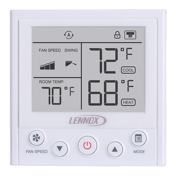
8. Daisy chain 2-conductor control wiring to each additional indoor unit using the HB/HA terminals in the electrical control box of the indoor unit. Do not daisy chain the +12V power cable or the COM wire. See Figure 6. NOTE - Wiring is polarity sen- sitive. - Page 8 Description of Buttons & Display Cooling Heating Auto Mode Mode Mode Mode Mode Locked Function Centralized Fan Speed Controller Locked Cooling Swing Setpoint Room Heating Temperature Setpoint Mode Speed Button Button Down-Arrow Up-Arrow Power Button Button Button...
-
Page 9: Operation
Operation NOTE - Indoor units connected to a local controller may also be controlled by a centralized controller. Indoor units respond to the last command sent. It is recommended that indoor units be controlled from a single source of control, either local controller or centralized controller but not both, to avoid conflicts in commands. - Page 10 Louver Swing Operation Press both the up-arrow button and the down-arrow button simultaneously to change lou- ver auto swing operation, specified position and stop as shown in Figure 7. Do not move louvers manually; only move louvers using the louver swing function on the controller. NOTE - Not available on all indoor unit types.
-
Page 11: Controller Settings
Centralized Controller Locks Controller If a function of the indoor unit is locked by a centralized controller (e.g. mode, temperature setpoint, swing, etc.), the V0STAT54P controller will not be able to adjust that locked func- tion. The function must be unlocked at the centralized controller before the local controller can operate it. - Page 12 Table 2. Controller Settings Function Value Description Note When Auto mode is being used, the controller will Power off – memorize the user setting of Memory settings on (default) Auto mode before powering for Auto Mode off. When power is restored, NOTE –...
- Page 13 Function Value Description Note Lock the maximum heating setpoint on the controller. Maximum 62-86°F 86°F (30°C) The Lock icon will display heating (17-30°C) (default) on the controller when this setpoint limit setting is set to anything other than the default. Lock the maximum cooling setpoint on the controller.
- Page 14 Function Value Description Note From individual Return air sensing takes indoor unit place at the indoor unit. Room tempera- From controller Return air sensing takes ture sensor (default) place at the controller. location Return air sensing takes From # indoor 00~62 place at the specified indoor unit...
- Page 15 Function Value Description Note 1°F/.5°C Set the setpoint resolution. Setpoint (Default) Cooling/heating will begin Control when the room temperature Resolution is the set value above or 2°F/1°C below the setpoint. 15 minutes (default) Auto mode Set the minimum time gap 30 minutes change over between heating and cooling...
- Page 16 Function Value Description Note Set the indoor unit external static pressure, only applies External Static Set value * 25 in. 0~25 to ducted indoor units. One Pressure wg (10Pa) controller to one indoor unit connections only. 59°F (15°C) When the indoor unit is in 59°F(15°C) default heating, when the coil tem-...
- Page 17 Function Value Description Note OFF (default) Low speed Indoor unit fan Medium speed Set the indoor unit fan status setting when when heating is satisfied. heating satisfied High speed Maintain last speed Reserved Reserved Reserved No aux/alt heat installed (default) Auxiliary/Alter- Aux/alt heat Set the installation scenario...
- Page 18 Function Value Description Note 2°F/°C 2°F/°C 3°F/°C 3°F/°C (default) The AUX/ALT contact will 4°F/°C 4°F/°C Auxiliary heat close when the room tem- perature is set value lower 5°F/°C 5°F/°C than the setpoint. 6°F/°C 6°F/°C 7°F/°C 7°F/°C -4°F/°C -4°F/°C -3°F/°C -3°F/°C -2°F/°C -2°F/°C -1°F/°C...
- Page 19 Function Value Description Note Dehumidifier Disabled (default) Enable/Disable the dehumid- contact control ifier contact control cut off. Enabled cut off enabled 3°F/°C 3°F/°C Set the lowest limit for the Dehumidifier dehumidifier contact control. 4°F/°C 4°F/°C (default) contact control When the room temperature cut off value reaches the setpoint less 5°F/°C...
- Page 20 Function Value Description Note Unlocked Lock/Unlock the Mode (default) button. When locked, the Lock Mode Mode button on this control- button ler becomes disabled. The Locked indoor unit mode cannot be changed from this controller. Unlocked Lock/Unlock the ON/OFF (default) button.
- Page 21 Indoor Unit Information Query • Press the Mode button and hold for 3 seconds to enter the indoor unit query. • Press the Up-arrow and Down-arrow buttons navigate to the next/previous the indoor unit address. • Press the Fan speed button to view the selected indoor unit indoor information. Total Indoor Unit Quantity...
- Page 22 • Press the Up-arrow and Down-arrow buttons navigate to the next/previous query num- ber. • Press the Fan speed button again to return to the previous screen. Upper Lower Query Number Figure 9. Indoor Unit Information See Table 3 for details about each indoor unit information query.
- Page 23 Table 3. Indoor Unit Information Location Description Value Upper Cooling setpoint 62~86°F (17~30°C) Lower Heating setpoint 62~86°F (17~30°C) Upper Indoor room temperature sensor Lower Upper Lower Upper Indoor EXV opening (thousands+hundreds) Lower Indoor EXV opening (tens + ones) Upper Room temperature sensor location Lower Controller room temperature sensor Upper...
- Page 24 Location Description Value Upper Contact 04# Lower Contact 04# status Upper Contact 05# Lower Contact 05# status Upper See indoor unit Lower Indoor unit type type table Indoor unit capacity/kbtu Upper (thousands+hundreds) Lower Indoor unit capacity/kbtu (tens + ones) Upper Lower Controller software version Upper...
- Page 25 Table 4. Indoor Unit Type Value Description V33B - 3x3 Cassette VWMB - Wall-Mounted VMDB - Medium Static Pressure Ducted VVCB - Vertical Air Handler VHIB - High Static Pressure Ducted V22B - 2x2 Compact Cassette VCFB - Ceiling & Floor Reserved Reserved Reserved...
- Page 26 Error Code Query • Press the up & down arrow buttons to • Press and hold the Mode button for 3 scroll through the fault codes. seconds to access the indoor unit sta- NOTE - At the fault code query screen, tus query.
- Page 27 Table 5. Indoor Unit Error Codes Error Code Description No address Mode conflict Communication error between indoor and main outdoor unit T1 (Room temperature sensor) malfunction T2 (Middle of evaporator sensor) malfunction T2B (Outlet of evaporator sensor) malfunction T2A (Inlet of evaporator sensor) malfunction DC fan motor error EEPROM failure EEV malfunction...
- Page 28 Table 6. Outdoor Unit Error Codes Error Code Description Communication error between outdoor units Power phase loss error Communication error between indoor and main outdoor unit Outdoor ambient temperature sensor (T4/T10) and condenser pipe temperature sensor (T3A/T3B) error Voltage error Inverter module temperature sensor error Discharge temp sensor error Incorrect ENC 1 main - sub configuration...
- Page 29 Error Code Description Quantity of indoor unit decreased High pressure sensor error DC fan module protection ( P9 10X in 120 minutes) Low pressure sensor error Sub ODU error Inverter module temperature protection ( 1PL / 2PL 3X in 100 minutes) PTC of DC filter board error ODU subcooler outlet temperature sensor error ODU subcooler inlet temperature sensor error...
- Page 30 Error Code Description Fan module protection Temperature protection of inverter module, CI/CO = 80/60 C or 176/140 F Low compressor discharge temperature protection Compressor inverter module error (Compressor inverter module protection) Low voltage protection of DC bus (Compressor inverter module protection) Over voltage protection of DC bus (Compressor inverter module protection )
- Page 31 Table 7. Mode Selection Box Error Codes Error Code Description Communication error between MS box to master outdoor unit Outlet of plate exchanger(subcooler) error Inlet of plate exchanger(subcooler) error Communication error between first PCB to the other PCBs in the same MS box S1/S2 setting is not consistent to communication wiring Table 8.
-
Page 32: Technical Support
Technical Support 1-844-GET-VRF1 (1-844-438-8731) vrftechsupport@lennoxind.com www.LennoxVRF.com Download the app from the Apple App Store or the Google Play store.
Need help?
Do you have a question about the V0STAT54P-3 and is the answer not in the manual?
Questions and answers
What is the error code FO