Table of Contents
Advertisement
Advertisement
Table of Contents

Summary of Contents for Kuppersbusch GKE 9851.0M
- Page 1 Service Manual GKE 6840.0M GKE 9851.0M...
- Page 2 Service Manual: H2-50-02 Responsible: Norbert Kirchmair KÜPPERSBUSCH HAUSGERÄTE AG Email: norbert.kirchmair@kueppersbusch.de Tel.: (0209) 401-718 Customer Service Fax: (0209) 401-743 Postfach 100 132 Date: 09.06.2011 45801 Gelsenkirchen...
-
Page 3: Table Of Contents
H2-50-02 Contents Safety ..........................4 Overview of the appliance ..................... 5 Description of the hobs and their output..............5 Control panel ......................6 Functions....................... 7 Technical data......................... 8 General features....................8 Technical data ....................... 8 Flame control......................8 Operation......................... 9 Operating the cooking zone burners .............. -
Page 4: Safety
H2-50-02 Safety Danger! Repairs may only be carried out by a qualified electrician! Improper repairs can be extremely dangerous for the user. It is essential that you observe the following instructions in order to prevent electric shocks: • The casing and the frame may be live in the event of faults! •... -
Page 5: Overview Of The Appliance
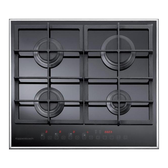
H2-50-02 Overview of the appliance Description of the hobs and their output Hob with an electronic cooking zone burner control system, with touch controls GKE6840.0M GKE9851.0M 1. Wok burner 3350W Fast burner 2800W Front left semi-fast cooking zone burner 1350-1400 W Back left semi-fast cooking zone burner 1750 W Extra cooking zone burner... -
Page 6: Control Panel
H2-50-02 Control panel Front left cooking zone burner minus key Front left cooking zone burner plus key 10 Back left cooking zone burner minus key 11 Back left cooking zone burner plus key 12 Back right cooking zone burner minus key 13 Back right cooking zone burner plus key 14 Front right cooking zone burner minus key 15 Front right cooking zone burner plus key... -
Page 7: Functions
H2-50-02 Functions Users and fitters have the following functions at their disposal: • Standby mode (cooking zone burner, keys activated). • Key lock as protection against unauthorised switch-on/settings. • 9-level setting of the volume of gas for each burner. • Safety interlock with manual resetting through release of the key. •... -
Page 8: Technical Data
H2-50-02 Technical data General features The basic features are listed here: • 7-segment display, red, with LED for displaying the volume of gas for each burner and for displaying the time and settings. • Touch-control with 15 sensor keys for setting the power level of the individual cooking zone burners and for the settings, locking the sensors and switching on and off. -
Page 9: Operation
H2-50-02 Operation Operating the cooking zone burners On the top of the hob a sign can be seen above every key, showing the burner to which the key relates. The cooking zone burners are ignited as follows once the gas tap or the gas bottle have been opened: 4.1.1 Switching the hob on Press the on/off key for at least 2 seconds to switch the hob on. -
Page 10: Other Functions
H2-50-02 Other functions 4.2.1 Setting the switching off time of a cooking zone burner A time can be set for each cooking zone burner, after which the cooking zone will automatically switch off. The clock key (11) must be pressed to programme a cooking zone timer. In the part of the touch control panel in which the position of each cooking zone is shown with an LED, the display of the front left cooking zone, for example, will light up to indicate that the front left burner has currently been selected for programming. -
Page 11: Setting The Clock
H2-50-02 4.2.2 Setting the clock The time of day shown by the hob's inner clock will have to be reset after a power failure. The clock key (11) and the key sensor (14) will need to be pressed simultaneously for at least 3 seconds to set the time of day. -
Page 12: Key Lock
H2-50-02 4.2.3 Key lock Activating the key lock The key lock is activated by pressing the key sensor for at least 2 seconds. The burners will remain at their current level. The key lock is displayed when the decimal points in the power level display of the individual burners light up. -
Page 13: Release Of A Cooking Zone Burner
H2-50-02 4.2.4 Release of a cooking zone burner A cooking zone burner which still does not ignite after three attempts will be blocked. When a burner is blocked, the letter “b” will appear in the power level display. The burner is released by pressing the minus key of the cooking zone on the front left (1) and the key sensor (14) for at least 2 seconds. -
Page 14: Installation
H2-50-02 Installation Important installation instructions The appliance can be installed with a tall unit on one side (on the right or left of the hob). The minimum clearances shown on the installation diagram must be maintained. The rear panel and the adjacent surfaces around the hob must be able to withstand an excessive temperature of 65K. -
Page 15: Mounting The Hob
H2-50-02 Mounting the hob The hob is fitted with a special sealing so that no liquids can get into the unit. The following instructions must be followed carefully in order to apply the sealing correctly: • Remove all the loose parts of the hob. •... -
Page 16: Gas Connection
H2-50-02 Gas connection The gas connection is carried out according to the following illustration. Burner ramp cables Connection Sealing Metallic supply pipe Instructions: • The gas intake connection of the appliance has a tapered screw thread for 1/2" gas according to EN 10226. -
Page 17: Replacing The Components
H2-50-02 Replacing the components The flanges must be removed when components in the hob are to be replaced. Loosen the screws and remove the glass ceramic hob. After carrying out the activities defined above, it will be possible to replace the electrically operated valves, the electric components and the electronic card. -
Page 18: Settings And Conversion To A Different Type Of Gas
H2-50-02 Settings and conversion to a different type of gas Replacing injectors The cooking zone burners can be adapted for different types of gas by mounting main injectors in compliance with the type of gas used. The burner heads will first of all need to be removed. Then use a straight spanner “B”... -
Page 19: Selecting The Type Of Gas Used For Cooking
H2-50-02 Selecting the type of gas used for cooking The hob can be adjusted for operation with natural gas (MET) or liquid gas (GPL). In order to activate the choice of gas to be used for cooking the hob must be ready for operation and all the cooking zone burners must be switched off. - Page 20 H2-50-02 Chart with the flow rates, the thermal output of the burners, the diameter of the injectors and the operating pressure of the various types of gas Table 3: Operating Injector Burners Thermal output Thermal output (W) pressure diameter Name mbar 1/100 mm min.
-
Page 21: Setting The Minimum Volume Of Gas For The Cooking Zone Burners
(7) and plus (8) keys of the burner at the front right simultaneously. • Model GKE 9851.0M: Press and hold the minus (1) and plus (2) keys of the burner at the front left and the minus (9) and plus (10) keys of the wok burner simultaneously. - Page 22 H2-50-02 Activation of a setting procedure is shown in the display (17) when “MIN” is indicated. Now the cooking zone burner that is to be set can be selected with the minus (12) or the plus (13) key of the programming for the clock.
-
Page 23: Fault Messages
H2-50-02 Fault messages The electronic circuit boards constantly check on their own status. If any problems with the hardware or defections of the circuit board occur which could have a negative effect on the safety of the end user, the appliance will switch to a “safe” status in which the electric valves are switched off. The code for the type of error appears in the display. -
Page 24: Electronic Unit Configuration
H2-50-02 Electronic unit configuration 10 11 12 Supply line Ionisation electrode, front right Ionisation electrode, back right Ionisation electrode, back left Ionisation electrode, front left Ignition transformer Master valve Valve, front right Valve, back right Valve, front left Valve, back left Not occupied For internal use only... -
Page 25: 10. Cooking Zone Valve Measuring Voltage
H2-50-02 10. Cooking zone valve measuring voltage Applied voltage (average value) for the respective type of gas: Natural gas Liquid gas 11.7 V 10.5 V-DC 12.1 V 10.9 V-DC 12.5 V 11.3 V-DC 12.9 V 11.7 V-DC 13.5 V 12.2 V-DC 14.1 V 12.8 V-DC 14.9 V...
Need help?
Do you have a question about the GKE 9851.0M and is the answer not in the manual?
Questions and answers