Table of Contents
Advertisement
Quick Links
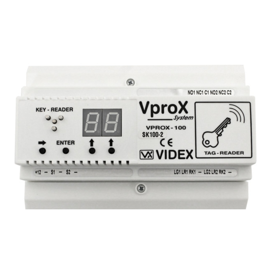
(2 DOOR, 100 KEY SYSTEM)
DESCRIPTION
The Vprox 100 is an advanced access control system based upon the VIDEX unique
Coded Key giving over 4 billion combinations. The system will operate and control two
independent doors and store up to 100 contact keys or proximity Tag or Card, each door
can also have an additional reader. Connections from the reader to the control equipment
can be made using un-shielded 5 core cable up to a distance of 200 meters, or a
maximum resistance of 10 Ohms.
Push to exit switches at each door will operate the associated relay in the control unit for
the programmed entry/exit time.
Security against sabotage, is maintained by having the VproX control equipment remote
from the reader heads. Should un-stored or un-qualified keys attempt to operate the
system, the control unit will disable all readers after every 5 attempts, the duration of the
readers disable time will increase if further attempts are made.
The control equipment has an LED display that confirms all data in programming mode,
and displays the key number when in the stand by mode (when key inserted).
The system has 4 push buttons for programming and modifying the information. Using
these buttons it is possible to :
Program a Master code to access the programming menu.
Program up to 100 unique keys or Tags with door access options.
To modify the settings and parameters of a stored key.
Delete one or more keys or Tags.
Program each door relay time (1 to 99 seconds)
INITIALISATION
When the installation has been completed (carried out in accordance with the supplied
Wiring Diagram), the system can be powered up and programmed following the VproX
100 Programming FLOW CHART, on completion the VproX 100 is ready for use.
NOTE: we suggest to separate the Mains lines (lift, electricity, electric lock, etc.) from
the readers connection line (at least 10 cm. far or use shielded cable for it) to avoid
electrostatic discharge and magnetic influence which could give control problems to
the CPUs present on the system.
OPERATION
In stand by mode the DISPLAY shows "--", when a stored key is inserted at any of the
reader heads the display will show the key number and which door is being operated
(decimal point position). When a stored key is inserted at any of the readers, the readers
LED's will display green and a sharp "beep" will be emitted. If the key is not
programmed the Display will show nothing and the readers LED's will display Red and a
low "beep" will be emitted
To operate relay 1 for the programmed time (door open) a n/o switch or short across
terminal "S1" to ground is required.
To operate relay 2 for the programmed time (door open) a n/o switch or short across
terminal "S2" to ground is required.
VIDEX VproX-100
1
VP100
Advertisement
Table of Contents

Summary of Contents for Videx VproX-100
- Page 1 (2 DOOR, 100 KEY SYSTEM) DESCRIPTION The Vprox 100 is an advanced access control system based upon the VIDEX unique Coded Key giving over 4 billion combinations. The system will operate and control two independent doors and store up to 100 contact keys or proximity Tag or Card, each door can also have an additional reader.
- Page 2 VIDEX VproX-100 (2 DOOR, 100 KEY SYSTEM) Programming overview The information below is to be used in conjunction with the programming flow chart. Standby : (The display shows [--]) Master code : The master code allows access to the programming menu.
- Page 3 VP100...
- Page 4 VIDEX VproX-100 (2 DOOR, 100 KEY SYSTEM) Lock release back EMF protection : A diode must be fitted across the terminals on the lock release to suppress back EMF voltages. The diagram below shows the polarity of the diode when fitted to the release.
- Page 5 VIDEX VproX-100 (2 DOOR, 100 KEY SYSTEM) Trouble shooting guide The display does not show [--] when you power up : Check the voltage across +12 & - on the cpu. Disconnect everything except the supply into the CPU and check again. (If the fault goes away check all connections and wiring again).
- Page 6 VP100...
- Page 7 VP100...
Need help?
Do you have a question about the VproX-100 and is the answer not in the manual?
Questions and answers