Table of Contents
Advertisement
Quick Links
Contents of "Declaration of Conformity"
Please refer the
EC DECLARATION OF CONFORMITY
in this manual as well.
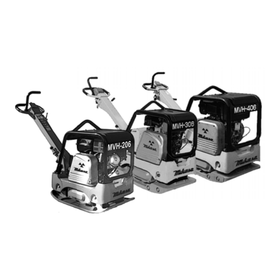
Thank you for your purchase of a
Mikasa Reversible Compactor.
For safe and correct use of this
p r o d u c t , p l e a s e r e a d t h i s
instruction manual before use,
and keep it for future reference.
Original
Advertisement
Table of Contents

Summary of Contents for Youngman Richardson & Co Mikasa Sangyo MVH-206
- Page 1 Contents of “Declaration of Conformity” Thank you for your purchase of a Mikasa Reversible Compactor. For safe and correct use of this p r o d u c t , p l e a s e r e a d t h i s instruction manual before use, and keep it for future reference.
-
Page 2: Table Of Contents
TABLE OF CONTENTS Preface Applications, Warnings, Power Transmission Of Machine Warning Symbols Safety Precautions General Precautions Refueling Precautions Location And Ventilation Precautions Precautions Before Starting Work Precautions During Work Lifting Precautions Transportation And Storage Precautions Maintenance Precautions Labeling Position 4.10 Label List 4.11 Description Of Symbols For Warning Labels Specifications Specifications Of The Machine... -
Page 3: Preface
1. Preface This operation manual describes the proper operation, basic inspection and maintenance procedures of the reversible compactor. Please read this operation manual before use in order to maximize the excellent performance of this machine and make your work more efficient and effective. After reading the manual, please keep it in a handy location for easy reference. -
Page 4: Warning Symbols
3. Warning Symbols The triangle marks ( ) used in this manual and on the decals on the machine are warning symbols. Please follow these precautions. Warning symbols indicating personnel hazards Extremely hazardous. If the warning is not followed, it is likely to result in serious injury or death. Hazardous. -
Page 5: Location And Ventilation Precautions
4.3 Location and ventilation precautions Do not run the machine in an unventilated location, such as indoors or inside a tunnel. The exhaust gas from the engine contains toxic gases such as carbon monoxide and is very hazardous. Do not operate the machine near open flames. 4.4 Precautions before starting Check each part to see if it is tightened properly. -
Page 6: Maintenance Precautions
4.8 Maintenance precautions Appropriate maintenance is required to ensure safe and efficient operation of the machine. Always pay attention to the machine’s condition and keep it in good condition. Pay special attention to the parts used for lifting, if they are not maintained properly, it might result in a serious accident. -
Page 7: Labeling Position
4.9 Labeling Position MVH-206 MVH-207 MVH-306 MVH-406... -
Page 8: Label List
4.10 Label List MVH-206/207 LABEL PART No. PART NAME Q’ TY MODEL REMARK PLATE, SERIAL NO. 9209-00110 DECAL,DO NOT LIFTING (ICON) NPA-1473 9209-00110 DEAL,LIFTING POSITION (ICON) NPA-1474 9209-00110 DECAL, WARNINGS (ICON) NPA-1475 DECAL, START,STOP/G (ICON) NPA-1476 9209-00110 9202-14950 DECAL, PULL OUT KEY(ICON) NPA-1495 206/207DS 9202-14960... - Page 9 4.11 Descriptions of symbols used on warning labels Do not use. (For rollers) NPA-1476 MVH-206GH NPA-1473 MVH-306GH MVH-306GEN Do not use. (For rollers) NPA-1475 NPA-1474 Refueling Hazard. Read the manual carefully. Always read the operation manual and have Don't fill the fuel tank while the engine is good understanding of operation before your running or hot.
-
Page 10: Specifications
5.Specifications 5.1 Machine specifications M V H - M V H - M V H - 306DS M V H - M V H - 406DS M V H - M V H - 207D M V H - Model (306DSNC) 206D 206G H... -
Page 11: Appearance
6. Appearance 6.1 Outside Dimension MVH-206 / 207 MVH-306 / 406... -
Page 12: Control Unit Positions And Names
6.2 Control Unit Positions And Names 6.2.1 MVH-206 / 207 6.2.2 MVH-306 / 406... -
Page 13: Inspection Before Operation
7. Inspection Before Operation Clean each part of the machine well to maintain dirt and dust-free condition. Pay special attention to the soil attached to the bottom of the compacting board, engine cooling air inlet, and the carburetor and air cleaner area Do not move travel lever to keep those parts clean. -
Page 14: Operation
8.Operation 8.1 Starting Gasoline engine Set the fuel cock lever to the “Out” position to let the fuel flow. (Fig. 4-1, 4-2) Fuel cock (HONDA) Fuel cock (ROBIN) Fuel cock lever FLOW Fuel cock lever Fig.4-1 Fig.4-2 In cold weather or when the engine does not start easily, set the choke lever to the “Start”... - Page 15 Hold the recoil starter grip, and pull it a little. You will feel a slight resistance. Then, pull it hard to run the engine. be careful not to pull too hard, or the rope might break or come off. Allow the starter rope to slowly move back into the case while keeping the grip grabbed.
- Page 16 Diesel engine Open the fuel cock lever. (Fig 10) Fuel cock Close Open Fig.10 Open the throttle lever to about 30° for the idling Throttle lever position. (Fig.11) Open by about 30degress. Throttle lever Fig.11 Cell starter / recoil starter Cell starter Insert the key to the key switch.
-
Page 17: Operation
Recoil starter : Do not pull the rope completely. Allow the start knob to slowly move back while keeping the knob grabbed. If you let the knob off your hand, the rope will suddenly move back, resulting in damage of the knob, engine, or the main body. If you pull the starting knob slowly, you will feel some Recoil starter resistance at a point (the compression point). -
Page 18: Compaction Sensor (Compass)
8.3 Compaction Sensor (Compass) Compaction sensor (Compass) is a system that uses acceleration sensor to show real-time soil Normal operation (Green: Lighted) Vibration abnormality (Green: Flashing) stiffness with LED (light-emitting diode) lights based on the number of compactions done. Compaction limit (Yellow + Red: Lighted) This compaction sensor improves efficiency of Soil problem (Only red: Lighted) compaction work because it can prevent the area... - Page 19 Function to detect abnormality Detection of ground trouble and soft ground For a case of unstable ground or soft ground (soil containing clay) for which the use of this machine Ground trouble or soft ground (Red only: Lighted) is not suitable, only the red LED lights up, with no yellow LED illuminated.
-
Page 20: Stopping The Machine
9. Stopping the machine Move the throttle lever from ON to OFF (for diesel engine, to idle position). Run the engine for 3 to 5 minutes at low speeds to cool it down before stopping. Diesel engine Move the throttle lever to the stop position to stop the Key switch engine. -
Page 21: Transportation
10 Transportation Make sure there is no breakage of guard frame and anti-vibration rubber nor loosened or missing bolts. Always stop the engine when lifting. Use an intact wire rope without any deformation with sufficient strength. Slowly lift upward without applying any impact. Never let people or animals go under the lifted machine. -
Page 22: Inspection And Maintenance Schedule Table
12. Regular check and adjustment 12.1 Inspection and maintenance schedule table For details about the check and maintenance of the engine, please refer to the attached engine operation manual. Caution: The above table shows the check frequency for standard condition. The check frequency may vary depending on the condition in which the machine is used. -
Page 23: Changing Engine Oil
12.2 Changing the engine oil Perform the first engine oil change after 20 hours of operation, then change at every 100 hours. 12.3 Cleaning the air cleaner The Engine Air Cleaner When the air cleaner element becomes dirty, the engine does not start smoothly, and sufficient output cannot be obtained. -
Page 24: Checking/Changing Vibrator Oil
Be careful not to get your hand caught between the belt and clutch pulley. Injury may occur. Wear gloves when performing this operation. (Fig. 28) Checking the clutch Check the clutch when checking the V-belt. Remove the belt cover and check for any seizing on the clutch outside drum. -
Page 25: Checking/Changing The Hydraulic Oil
Checking/changing the hydraulic oil Check the hydraulic oil Plug cap Check the hydraulic oil at every 100 hours’ operation. By Breather making the handle bar vertical (done at the time of plug storage), remove the breather plug at the top of the hydraulic hand pump to see if the hydraulic oil is at the OIL LEVEL specified level (OIL LEVEL). -
Page 26: Checking/Changing The Battery
12.7 Checking/changing the battery The standard battery installed is a maintenance free battery. It is not necessary to supply battery fluid. In case of a sudden voltage drop, the battery cannot be charged quickly, so it has to be replaced with a new one. Removing the battery (Fig. -
Page 27: Troubleshooting
13. Troubleshooting 1. Gasoline engine (1) Starting problem Bridging the igniter plug. Carbon accumulated on the igniter plug. Short circuit due to insulation problems of Electricity reaches the igniter plug. the high voltage cable. Inappropriate spark gap Fuel is supplied, but the igniter plug does Short circuit of the ON-OFF switch not ignite. - Page 28 2. Diesel engine (1) Starting problem (A) In case of compression problems Intake/exhaust valve upthrust No compression at all Decompressor adjustment problems Contact with seat not close enough. Piston ring wear Almost no compression Cylinder wear Cylinder, cylinder head mating surface problems Nozzle seat looseness (B) In case of inappropriate fuel injection inside the combustion chamber Clogging of the tank cap air hole.
- Page 29 Valve open/close timing inappropriate Engine revolution Clogged exhaust hole, muffler does not increase. Overload Piston, cylinder ring wear Nozzle hole clogging Piston ring stuck Wrong assembly (upside down) of piston ring Inappropriate injection timing Inappropriate valve open/close timing Looseness of injection pump joint Leakage from fuel passage Fuel consumption too Clogging of the air cleaner element...
- Page 30 14. Wiring Diagram MVH-306 MVH-406 SUMITOMO Sky-blue Oil pressure switch Orange SUMITOMO Dynamo Starter BOLT ( Green/ ( Green/ White) White) White ( Green/ ( Green/ White) White) Regulator YAZAKI White Black White Green YAZAKI MVH-306-PAS BOLT MVH-406-PAS Compaction SUMITOMO sensor panel Oil pressure Sky-blue...
Need help?
Do you have a question about the Mikasa Sangyo MVH-206 and is the answer not in the manual?
Questions and answers