Advertisement
Quick Links
Introduction of the New Model
NB20 system adopts the latest RF technology, providing very high adjacent
channel rejection ratio and anti-blocking performance, which gives rise to the
outstanding anti-jamming capability of the new system. NB20 receiver can detect the
frequency and amplitude of EMI interference with unbeatable accuracy and precision
based on the extremely low self-noise of -125dBm. The RF performance of NB20
system surpasses the older 4047 systems several orders of magnitude. Furthermore,
NB20 system takes high-speed processor for signal acquisition and output with very
high precision. Its high efficiency transceiver can make full use of band width
limitation and spend shorter time to work out data exchanging,and frequency
calibration. As for operation, NB20 system is compatible with any receiver to
construct a signal relay system. It is highly compatible with mature products on the
present market, such as FUT, JR, HITEC, TDF, FS, XINYI etc. There is no need for
consumers to change the old remote control system or any parameter settings to
directly extend the remote control range. PWM output-and-input is one-to-one. It can
relay signal with very high precision. By using the powerful forwarding of 20
channels, UAV's parameter can be adjusted in the air, and the aerial cameraman and
pilot could work together with single radio. In addition, one transmitter can be shared
by several operators. As for the receiver, either EMI or RSSI signal can be displayed
on LED, which allows debugging according to the visual signal strength. The new
system is of longer remote control distance and higher reliability, because the source
of interference can be more quickly and accurately ruled out.
Advertisement

Summary of Contents for RMILEC 4047NB20
- Page 1 Introduction of the New Model NB20 system adopts the latest RF technology, providing very high adjacent channel rejection ratio and anti-blocking performance, which gives rise to the outstanding anti-jamming capability of the new system. NB20 receiver can detect the frequency and amplitude of EMI interference with unbeatable accuracy and precision based on the extremely low self-noise of -125dBm.
- Page 2 Differences (Values below are typical.) Differences New model 4047NB20 Old Model 4047 Average RF 5w (peak number is 5.8W ) 1.6w (peak number is...
-
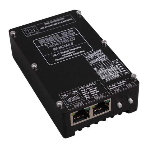
Page 3: Components And Functions
4047NB20 System Operating Instructions Components and Functions Transmitter RF output Output interface is 50 ohm SMA socket. RF socket need to be connected to the antenna during the operation. If RF socket is open circuit or short circuit, the amplifier... - Page 4 Power and Data socket DATA1: Data and power input socket 1 Input data is PPM or UART digital signal, which can be switched through SW3.Voltage range is 10~14VDC, typically 12VDC. Exceeding normal range of operation will result in increasing failure rate, or even permanent damage. DATA2: Data and power input socket 2 Functions are the same as DATA1.
- Page 5 DIP Switch SW1 is designed for RF power selecting. “ON” indicates high-power mode, of which output power is 5W. The RF output warning tone is do, re, mi, fa.. “OFF” indicates low-power mode, of which output power is 2W. The RF output warning tone is do, re, mi.
- Page 6 is used for directly connecting to the remote control equipment. “OFF” indicates DATA1 and DATA2 can only input digital signal. It is used to connect the signal acquisition system. Note: When using the PPM signal, please select low power mode in order to avoid distortion of the PPM signal and the crash of remote control equipment.SW3 can only take effect when it is set before the transmitter power on.
- Page 7 Buttons PB1: The transmitter will be switched to binding mode by pressing this button before power on the transmitter. Keeping pressing this button for 5 seconds after power on the transmitter, the current servo position data will be stored in the receiver. PB2: The receiver will be switched to the data copy mode by pressing the PB2 button before power on the transmitter.
- Page 8 RJ45 LED LED1: Valid data input indicator,of which lighting up indicates that valid data is being input. The data is PPM or 20CH digital data. LED2: RF output indicator,of which lighting up indicates that the current input data is being emitted into the air by the RF. The meaning of Warning Tones do, re, mi Starting to transmit in 2W mode...
- Page 9 Signal Acquisition System Power Terminal 12V DC power input Data Terminal...
- Page 10 PIN1, PIN15 are ground. Connected to the negative terminal of the be-relayed receiver. PIN2, PIN16 are 4.8V positive power supply output, connected to the positive power of the be-relayed receiver. Note: PIN1-PIN2 and PIN15-PIN16, which internally parallel, can provide two be- relayed receiver .
- Page 11 avoid cumbersome wiring. The PPM indicator lamp will light up when the valid PPM signal is detected. Note: PIN13 can input PPM containing 14 channels of data, while the the PPM signal rate should be larger than 30Hz. Moreover, the PPM content should be more than 4 channels of data, otherwise it will be considered as invalid signal or error signal.
- Page 12 condition, leading to accident. Only CH3 and CH13 can be configured to throttle channel. If you want to use other channels to control the throttle, please handle it with caution. You should correctly set failsafe of R4047NB20 to avoid accidents. RJ45 ELD LED1: no signal input.
- Page 13 Receiver Receiver Pin Definitions PIN1-PIN10 are CH1-CH10 PWM output PIN11 is CH1-CH10 PPM output PIN12 is CH1-CH18 SBUS output (compatible with the FUT SBUS) PIN13-PIN22 are CH11-CH20 PWM output PIN23 is CH11-CH20 PPM output PIN24 is RSSI output, which the maximum current is 20mA with 50 Ohms internal resistance.
-
Page 14: Signal Strength Indicator
Buttons Press BIND and power on the receiver, then it will move to binding mode or copy mode. Press SCAN, and power on the receiver, then it will move to the interference scan mode. Common Indicators RF RX: When the receiver RX or TX (there is RF output under binding mode) RF RX LED will light up. -
Page 15: Transmitter Installation
X: RSSI voltage Unit is mV. Examples as follows: If the measured RSSI voltage is 900mV, according to the above formula, 900/20-120 = -75, then the actual received RSSI is-75dBm. If the measured RSSI voltage is 0.1V, according to the above formula, 100/20-120 = -115, then the actual received RSSI is-115dBm. - Page 16 The picture above shows the use of hand-held antenna. The picture above shows the use of car antenna(RG402 cable is recommended). Data Interface and Power Supply Connection The data interface is RJ45 interface, connected to the signal acquisition system with a flat 8-pin data cable. The signal acquisition system is powered by large capacity batteries or by a car cigarette lighter.
- Page 17 Powered by a Cigarette Lighter The Connection with the be-relayed receiver Be-relayed receiver connect the SBUS signal to the signal acquisition system, or connect the PWM signal needed to be transmitted to any of the PWM input pin on the acquisition box.
- Page 18 12FG settings allows the sync-transmit of 4047NB20 system and the 12FG. Under sync-transmit, 12FG powers on coupled with the 4047NB20 starting. And when 12FG is off, the 4047NB20 move to IDLE mode. The configuration of 12FG is as followed: The picture above shows FUNCTION settings.
- Page 19 The picture above is 5-8CH Fail-Safe setted to HOLD, CH12 F / S +100%. The picture above is the SBUS Connection. NOTE: There has to be no electronic device within 30cm of the transmitter antenna, including the signal acquisition system and the be-relayed receiver. Because the strong radio influence is very likely to cause signal instability and it may also cause the malfunction or permanent damage of the be-relayed receiver.
- Page 20 Anti-Interference and Safe Cabling Measures The picture above shows safe cabling method for the handheld antenna. There is no electronic device within 30cm around the transmitter antenna.
- Page 21 If you use the car antenna, there is no need to worry much about the safe cabling in the car. The car antenna uses the RG402 cable or batter cable. The Installation of Cooling Fan Under high-power mode, you need to install cooling fans. You can firmly adhere it to the back of the transmitter with double-sided adhesive tape.The fan can be powered by any of the RJ45 socket on the transmitter.
- Page 22 Erection of Transmitter Antenna One of the ways to install the transmitter is to elevate it by using a tripod or the roof, and the transmitter will be fixed by screws or adhesive tape. Another way is to install it in the car, using RF cable to connect with the transmitter. The picture above shows the elevated antenna on the balcony.
- Page 23 The picture above shows the car antenna installation. The RD6014 needs to be fixed on the inside glass of the car.
-
Page 24: Receiver Installation
Note: Before locking your car, check whether the transmitter interferes with the locker to ensure that you can open the door. Receiver Installation Receiver installation During the receiver installation, relatively similar to gyroscope, the shock absorbing sponge is needed. Otherwise in the strong shock, Frequency drift of TCXO will reducing the signal quality. - Page 25 Note: The receiver antenna should not be too close to high-power RF output sources or T4047NB20’s antenna, otherwise the receiver will be permanently damaged or the signal will be blocked. The Recommended Layout of Installation The picture above shows the location of the receiver in the cabin.
- Page 26 The picture above shows the position of ANT1 . The picture above shows the position of ANT2 and video transmitter. The video transmitter uses the RG402 cable, which is the same as the car antenna cable.
- Page 27 The picture above shows the location of the image transmitter antenna. The picture above shows the position of the GPS antenna. Binding and Copying the Frequency Hopping Data Binding 1 Turn on all of the peripherals, the video transmitters, GPS, the autopilot, the video recorder and cameras.
- Page 28 6 The transmitter will sound continuous alarms when received the scanning report. 7 The binding is completed The third and fourth steps can be reversed Note: The bound receiver is unique ( the same as the TS4047 system), that is, if re-bound with other receivers, the previously bound receiver will be automatically blocked.
- Page 29 The Settings of Failsafe After the system work normally, press the PB1 for 5 seconds to save the position data of every servo to the receiver R4047NB20. The failsafe data takes effect only when SW2 is OFF. If the SW2 is ON, once out of control, the servo will keep the last position.
- Page 30 Under normal circumstances, the LED2 will light, while in the excellent case, only LED1 will light. Lighting up of LED3 represents that you need to adjust the position of airborne equipment. Step three, adjust the position. The objects that need to be adjusted are the EMI interference sources.
-
Page 31: Common Troubleshooting
4. The signal acquisition system is connected with the SBUS wire of R6203SB and R6203SB is powered with 4.8V power supply. The signal acquisition system itself has power supply output. So the connection to R6203SB just needs three wires. If there is no SBUS receiver, a lot of wires are in need to connect PWM out to PWM in one by one. - Page 32 CH5 switch, now try the CH6 or try CH7 and CH10 to judge whether it is the problem of the 4047NB20 system itself, or put CH4 to CH5 to see whether the CH5 can transmit normally.
- Page 33 8, Without a normal binding process, the probability of losing control will increase a lot. 9, If the receiver is tested without its antenna, you can only know whether the receiver works or not. It does not show whether the interference among the airborne devices.
Need help?
Do you have a question about the 4047NB20 and is the answer not in the manual?
Questions and answers