Table of Contents
Advertisement
Cleveland Open Cup
Automatic Flash Point Tester
Asphalt Version with Data Memory
IMPORTANT:
*This Manual contains important technical
information as wall as safety information.
*Read this Manual thoroughly before use, and
keep it for later use.
TANAKA SCIENTIFIC LIMITED
Model ACO-7
Instruction Manual
Rev.5.1 100414
- 0 -
Advertisement
Table of Contents

Summary of Contents for Tanaka ACO-7
- Page 1 Cleveland Open Cup Automatic Flash Point Tester Model ACO-7 Asphalt Version with Data Memory Instruction Manual Rev.5.1 100414 IMPORTANT: *This Manual contains important technical information as wall as safety information. *Read this Manual thoroughly before use, and keep it for later use.
- Page 2 CAUTION Handling for Fire Containment Lid of ACO-7 When Fire Containment Lid is not set in the proper place, it does not operate correctly. 1. To set it correctly, please push the Reset Knob which is located on the right side...
- Page 3 2. How to check Correct position & Wrong position Wrong position Correct position Slit can be seen Slit cannot be seen Hook is positioned inside of the catch Hook is positioned out of the catch...
-
Page 4: Table Of Contents
INTENDED READER OF THIS MANUAL …………………………………. 4 REVISIONS ……………………………………………………………...……... 4 SAFE OPERATION …………………………………………………………… 4 WARNING ……………………………………………………………………... 5 1. Overview of Model ACO-7 ………………………………………………..6 2. Installation …………………………………………………………………… 9 2.1 Installation Site …………………………………………………...………. 9 2.2 Electric Connections …………………………………………..………….. 9 2.3 Gas Connection ……………………………………..…………………….. 9 3. -
Page 5: Forward
CAUTION : Indicates a potentially hazardous situation which, if not avoided, may result in minor or moderate bodily injury and/or property damages. And also the WARNING LABELS are put on the body of ACO-7. The meaning of these labels is as follows. -
Page 6: Warning
Alteration: Do not make any modification to the Tester, in whole or a part, or add any unauthorized accessories to the Tester without prior consent by Tanaka Scientific Limited(hereinafter referred to as Tanaka). We can not take any responsibilities for damages, including but not limited to property and/or bodily damages, associated with the alteration of Tester. -
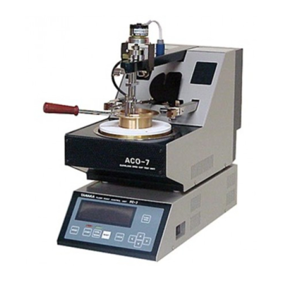
Page 7: Overview Of Model Aco-7
Switch Fire Containment Lid Arm Handle Temperature Sensor Thermofus Flash Detector Rings Reset Knob Flame Size Comparison Bead Skimmer Shaft Dual Electric Pilots (Igniter Top) MAIN Switch Manual Fire Containment Switch Fig. 1 External View of Model ACO-7 Asphalt Version... - Page 8 MAIN Switch: Used for switching power source to the Tester. Panel Sheet Switch: Consists of START, COOL, RESET switches as well as switches for changing test parameters. Display: Displays test status and result as well as test parameters. Flash Detector Rings: Detects flash by ionization current between each rings.
- Page 9 FUNC TION (11) (10) COOL MODE START RESET CHECK WARM Fig. 2 Operation Panel and Display of Control Unit (1) Fluorescent Display: Displays test mode, specimen temperature, flash point (when blinking), expected flash point, trouble message, etc.. (2) RUN Lamp: Illuminates when a test process is in progress.
-
Page 10: Installation
2. Installation 2.1 Installation Site Install the Tester on a draft-free, level and stable table. The Tester needs to be placed at least 20cm away from other objects. The following locations should be avoided as the installation site: - An area with high temperature and/or high humidity - An area exposed to direct the sun - An area with poor ventilation and/or dusty air - An area subject to rapid changes in ambient temperature... - Page 11 Test Unit Signal Connecting Cable Gas Inlet Circuit Protector Control AC Outlet Unit RS-232C Connector Power Connecting Cable AC Power Cord Fig. 3 Rear View and Electric Connection...
-
Page 12: Operation
Fig. 4 Main Screen 3.2 Confirming a Barometric Pressure Value ACO-7 is capable of making automatic correction for barometric pressure by built-in barometric pressure sensor. Confirm the barometric pressure every morning as follows: (1) Press FUNCTION key, The display shows Baro set screen as illustrated in Fig. 5 appears. -
Page 13: Select Test Mode
3.3 Select Test Mode ACO-7 Asphalt version has 2 kinds of test method and 5 kinds of test mode. Each ASTM and ISO method has each Normal mode, Special mode(Fast Search), Fire mode, Skim mode and User’s Custom mode. Fire mode and User’s Custom mode are invalid when shipping. The test method (ASTM or ISO) is selectable by changing DIP switch on the MAIN board. -
Page 14: User's Custom Mode
Automatic surface film skimmer works to attain the right test result when the setting temperature is reached. For the starting temperature and interval setting of skimmer, see 3.7. 3.3.5 User’s Custom Mode In this mode, heating rate, stirring speed, application interval and its start temperature can be changed by operator. -
Page 15: Start Of Ignition Source Application
F) when ASTM is selected as a test method, rounded to the nearest 2 C when ISO is selected as a test method and then displayed. For the selecting test method (ASTM or ISO), refer ACO-7 Maintenance Manual. Fc=F+0.025(1013-P1) where Fc: Corrected flash point F : Observed flash point : Entered (detected) barometric pressure value (hPa). - Page 16 Observed flash point can be seen by pressing FUNCTION key. In case a wrong pressure value has been entered, enter the right value and then press FUNCTION key; recalculated flash point will be shown. (2) When ASTM is selected as a test method, and a flash point is detected at first application of the ignition source, NG 1st appears right side of flash point.
-
Page 17: Completion Of A Test
The temperature display (flash point) is held until the RESET or START switch is pressed. *3: Cooling time is adjustable. Also selectable (do cooling or not). For changing cooling time, consult Tanaka authorized distributor. 3.5 Test by Special (Fast Search) Mode This mode is used for measuring an approximate flash point of a specimen of unknown expected flash point. -
Page 18: Test By Fire Mode
3.6 Test by Fire Mode WARNING Fire Containment Lid and pivot shaft be kept clean to function properly. Do the damper check before testing by fire mode. As some fire may not be extinguished completely by the Fire Containment Lid, the operator may have to extinguish the fire manually. -
Page 19: Data Storage Function
4. Data Storage Function (use this function with optional Built-in Clock Board) ACO-7 has a data storage function. Up to 50 successive data can be memorized. (*4) After ACO-7 detects a flash point, the data will be stored automatically. If Built-in Clock Board is not installed, actual date will not be memorized in DATE column. -
Page 20: In Case Of Abnormal Operation Or Trouble
Gas piping inside the Test Unit is made of nylon tube; outside, viton tube. Gas is very dangerous if it leaks. Consult the Tanaka authorized distributor for periodical gas leakage check. THE TESTER IS NOT EQUIPPED WITH A GAS LEAKAGE DETECTOR. -
Page 21: Post-Sales Servicing
Manual. 9. Caution when Transferring This Tester If this Tester is transferred or sold to a third party, please inform Tanaka or its authorized distributor. Wrong source voltage and/or AC frequency could cause damages or malfunctioning. - Page 22 (14) Standard Accessories: Description Quantity Test Cup Assembly Power Connecting Cable, 0.6m Signal Connecting Cable, 0.6m AC Power Cord, 2.5m (>AC200V) or 3.0m (<AC125V) Thermal Insulation (Heating Plate) Spare Thermofuse 3pcs Insulation tube for Thermofuse, 0.1m Spare Paddle 4pcs Gas Hose 9 x 16 x 1500mm Gas Hose Band 2pcs Instruction Manual...
- Page 23 3. If any faults occur due to normal use within the warranty, the product will be repaired free of charge. 4. Be sure to notify Tanaka Scientific Limited when repairs being requested are covered under the warranty. 5. The following faults or damage are not covered by the warranty: ▪...