Table of Contents
Advertisement
This manual details the features of the following SC2000 core controllers and variants.
1.
SC21xx
Integrated Traction + Pump Controller.
2.
SC22xx
Standalone Traction Controller.
3.
SC23xx
Standalone Pump Controller.
4.
SC24xx
Integrated Traction Dual Motor Non Proportional Controller + Pump.
5.
SC25xx
Integrated Traction + Traction Dual Motor Proportional Controller.
Revision
F
DT
Complete rewrite to reflect the new features introduced by version 6.XX software
G
JP
Add wiring diagrams. Change Index. Add Personalities 1.6.16 Fixed Plugging,
Work Hours Count 2.2.9 and Seat 2.3.11. Remove SC26XX variant and drawings
D.Thomson. 12
J. Punton. 22
nd
22
October 2004
SEVCON
SC2000 MANUAL
Revision History
th
December 1997 Issue F. (SC2MAN_F.doc)
nd
October 2004 Issue G. (SC2MAN_G.doc)
SC2000 Manual – 177/52301 Rev G
Comments
Page 1
Advertisement
Table of Contents

Subscribe to Our Youtube Channel
Summary of Contents for tech/Ops SEVCON SC2000 Series
- Page 1 SEVCON SC2000 MANUAL This manual details the features of the following SC2000 core controllers and variants. SC21xx Integrated Traction + Pump Controller. SC22xx Standalone Traction Controller. SC23xx Standalone Pump Controller. SC24xx Integrated Traction Dual Motor Non Proportional Controller + Pump. SC25xx Integrated Traction + Traction Dual Motor Proportional Controller.
-
Page 2: Table Of Contents
CONTENTS INTRODUCTION ......................... 3 SC2000 CONTROLLER VARIANTS ................... 4 CONTROLLER FEATURES ....................5 SAFETY..........................6 TECHNICAL SPECIFICATIONS ..................7 CONTROLLER CONNECTIONS..................10 CALIBRATOR AND ADJUSTMENTS................14 DIAGNOSTICS ......................... 21 SERVICE AND FAULT LOGS ................... 22 CONTROLLER OPERATION AND FEATURE DESCRIPTIONS........23 10.1 TRACTION OPERATION .................. -
Page 3: Introduction
INTRODUCTION The SC2000 range of Controllers use a powerful microprocessor to control two power frames - Traction (with regen or plug braking) and Pump. Both power frames are integrated within one compact enclosure and use state-of-the-art mosfet technology. The SC2000 is available in a wide range of voltage/current variants and power-frame configurations. -
Page 4: Sc2000 Controller Variants
SC2000 CONTROLLER VARIENTS SCxxxx Model number description 1st digit Controller range identification (always 2) 2nd digit Controller 1 = Traction+Pump Type 2 = Traction 3 = Pump 4 = Traction+Pump Dual Motor Non Proportional 5 = Traction+Traction Dual Motor Proportional 6 = Traction Dual Motor Proportional... -
Page 5: Controller Features
CONTROLLER FEATURES The SC2000 range of controllers offer the following features: * 24-48V, 72-80V and 72-96V operation. Current limits of 500, 650A and 1000A. * Enclosed unit to IP34 with Field-replaceable logic. * Traction + Pump motor controllers in one enclosure. * Also standalone Traction and standalone Pump controllers available. -
Page 6: Safety
SAFETY Electric vehicles can be dangerous. All testing, fault-finding and adjustment should be carried out by competent personnel. The drive wheels should be off the floor and free to rotate during the following procedures. THE VEHICLE MANUFACTURER'S MANUAL SHOULD BE CONSULTED BEFORE ANY OPERATION IS ATTEMPTED. -
Page 7: Technical Specifications
TECHNICAL SPECIFICATIONS Environmental 5.1.1 Protection: The enclosure is protected to IP34. 1st digit (3) = Protection against objects > 2.5mm entering controller enclosure. 2nd digit (4) = Protection against low pressure jets of water in any direction. Limited ingress permitted. 5.1.2 Vibration: 6G, 40-200Hz for 1 hour, in x,y and z planes. - Page 8 5.3.2 Current specifications: Model Power Current Safe Continuous Current 1 limit operating Hour rating, with unit (1 min) Area (SOA) mounted on an Trac.+ aluminium baseplate Pump 780x380x10mm, at 20°C ambient. SC2x26 24V 2x650A 650A 30 - 60% 225A (1 side only) SC2x45 48V 2x500A 500A...
- Page 9 Three of the above inputs, pins 9, 10 & 21 have supply outputs associated with them, pins 11, 12 & 23 respectively. Various connection options are available. Voltage Range: 0V - 5.0V Using the calibrator, the minimum and maximum levels can be defined to equal any two voltages in the above range.
-
Page 10: Controller Connections
CONTROLLER CONNECTIONS Power Connections (Figs. 2 to 7) Power wiring must be made with 35mm cable (minimum). 6.1.1 Controller Connections - These are made via M8 terminals depending on unit configuration, as follows: All Controllers: Connected to Battery positive via the fuse and line contactor (if fitted). Connected to Battery negative. - Page 11 Note1: Line contactor is optional but can be fitted to offer reverse battery protection, minimise arcing when the battery connector is inserted and to provide a mechanical break for a Pump Controller. Note2: Any 2 of the Optional contactors (except Line) can be reassigned for use as the second set of direction contactors for dual motor traction systems.
- Page 12 Light Wiring Connections (Fig. 1) 6.2.1 Connector A - 24 way Pin Main Function Secondary Function Pin Type Forward Switch Digital Reverse Switch Digital FS1 Switch Digital Seat Switch Digital Handbrake Switch Digital Speed Cutback 1 Input Digital Speed Cutback 2 Input (Dual Motor Outer sw) Digital Pump Inhibit Input...
- Page 13 Pin Main Function Dual Motor Function Pin Type Line Contactor Digital * Forward Contactor (DM Right Motor Fwd) Digital * Reverse Contactor (DM Right Motor Rev) Digital Regen Contactor Digital * Bypass Contactor (DM Left Motor Fwd) Digital * Field Weakening Contactor (DM Left Motor Rev) Digital Power Steer Contactor...
-
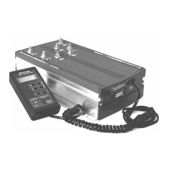
Page 14: Calibrator And Adjustments
CALIBRATOR AND ADJUSTMENTS A sophisticated, yet easy to use hand held adjustment unit, called the Can Calibrator is used to make adjustments to the controller and select configurations. The CAN Calibrator is also used as a diagnostic tool displaying the status of all voltages, currents and temperatures within the controller together with the condition of all the controller’s switch and analogue inputs. - Page 15 7.1.1 Traction Personalities (Controller Adjustments) Min setting Max.setting Max.setting Step size Cal.Ref Parameter Adjusted (all units) (500 A unit) (650 Aunit) (all units) 1.1.1 Current limit 50 A 500 A 650 A 10 A 1.1.2 Acceleration delay 0.1 s 5.0 s 5.0 s 0.1 s 1.1.3...
- Page 16 7.1.2 Traction Status Information Cal.Ref. Parameter Displayed Min.Display Max.Display Step size Log Info. 1.2.1 Battery Voltage 127 V 0.1 V 1.2.2 L/R Traction Motor Voltage 127 V 0.5 V 1.2.3 L/R Traction Motor Current 1200 A 1.2.4 L/R Traction Controller Temp. -30 °C +225 °C 1 °C...
- Page 17 7.1.5 Fault Log Can be disabled via setup menu. See section 9 for more details. 7.1.6 Setup Menu (Enables/Disables features) Cal.Ref. Feature Options 1.6.1 Contactor Chopping 24 V / On / Off 1.6.2 Accelerator Type Linear / Curved / 2* Slope/ Crawl 1.6.3 On / Off 1.6.4...
- Page 18 7.2.2 Pump Status Information Cal.Ref Parameter Displayed Min. Display Max.Display Step size Log Info. (all units) (all units) (all units) 2.2.1 Battery Voltage 127 V 0.1 V 2.2.2 Pump Motor Voltage 127 V 0.5 V 2.2.3 Pump Motor Current 1200 A 2.2.4 Pump Controller Temp.
- Page 19 7.3.1 Traction and Pump adjustment descriptions Adjustment Description (T=Affects traction, P=Affects Pump) Current Limit Maximum allowable motor current. Acceleration Delay Time taken to ramp up from 0 to 100% on. Deceleration delay Time taken to ramp down from 100% to 0% on. Creep Speed Minimum applied % on when drive first selected.
- Page 20 7.3.2 BDI adjustment descriptions BDI Adjustment Description Charge remaining Displays the remaining battery charge. This is a display only, no adjustments can be made. Battery Voltage Adjustment used to enter the nominal battery voltage Reset Volts/Cell Sets the voltage at which the BDI resets to 100% at power up. E.g. the BDI will reset to 100% on a 48V system, with the reset adjustment set to 2.20 Volts per cell, if the battery voltage is above 52.8V.
-
Page 21: Diagnostics
DIAGNOSTICS Traction and Pump Fault Messages and LED status/number of flashes Calibrator Standard Full Feature Led Description and how to clear Check... Message Display Display Traction operational and OK. No action required. (lowest priority) Testing... Only displayed briefly at power up. No action required. -
Page 22: Service And Fault Logs
SERVICE AND FAULT LOGS The Service and Fault Logs have been incorporated to allow end users and service personnel to inspect and note the controller’s performance and fault history. Utilising the controller’s existing Status measurements and Diagnostics capabilities, information (such as the maximum temperature the controller has operated at or the number and type of faults that have been detected) can be stored in non-volatile memory and presented at a later date. -
Page 23: Controller Operation And Feature Descriptions
CONTROLLER OPERATION AND FEATURE DESCRIPTIONS 10.1 TRACTION OPERATION 10.1.1 Start Up Sequence - At key switch on, the Direction and FS1 switches must be in the neutral condition simultaneously at least once before drive can be selected. This is a safety feature to help prevent unexpected movement immediately after power up. - Page 24 Bypass can be initiated in 2 ways: Current-limit Bypass: the accelerator is fully depressed and the controller has been in current limit for longer than 2 seconds. In order to prevent a sudden lurch of the truck the contactor will not be energised if the motor voltage during current limit is less than 20% of battery voltage.
- Page 25 Regen Braking - Regen provides vehicle braking by controlling the motor as a generator and 10.1.12 returning the generated energy back to the battery. Regen braking reduces motor heat dissipation compared with plug braking. Regenerative braking can be initiated in 3 ways, each with an independently settable braking level, as follows: i) A direction switch change will initiate regen braking at a level set by the Direction Brake Current level.
- Page 26 10.1.15 Inching - This facility is normally used on Tow Tractors to manoeuvre the Tractor towards the load from the rear of the vehicle, using 2 inching buttons, one for forward and one for reverse. The inch speed is adjustable via the calibrator. Inching will only operate if the main direction control and FS1 switches are in the neutral position and the seat switch is open, and handbrake off.
- Page 27 10.1.21 Steering Potentiometer - For Dual Motor traction applications, the footbrake input can be reassigned to be a steering potentiometer input. 10.1.22 Digital Switch Inputs - The digital inputs on the controller can be configured as Active Low inputs, where the switches are wired to B-ve, or as Active High inputs where the switches are connected to B+ve.
- Page 28 10.1.25 Fail-safe The controller’s safety system includes a microprocessor watchdog which can detect software failure, and a hardware fail-safe system which can prevent dangerous runaway conditions in the event of certain hardware failures. Every time the controller is powered-up, the software checks that the fail-safe circuit is able to switch off the Mosfets and open at least 2 contactors.
-
Page 29: 10.2 Pump Operation
10.1.28 Speed Limit - A traction speed limit in KPH can be set via personality 1.1.28 (0 KPH disables the feature). As the speed of the vehicle approaches the limit, the maximum motor voltage is reduced. If the speed limit is exceeded by more than 2 KPH (when the vehicle is travelling down-hill for example) electrical braking will be used until the speed of the vehicle falls to below the limit. - Page 30 10.2.5 Power Steer speed - On compensated pump systems this setting can be used to control the power steer speed from the main pump motor. This speed is selected from the power steer trigger input as previously described and can be compensated for as described in the section below.
-
Page 31: 10.3 General Operation
10.3 GENERAL OPERATION 10.3.1 Operating Frequency The drive frequency of both the Traction and Pump power frames is 15.67Khz, for silent operation. For Traction plug and regen-braking the frequency is also 15.67Khz and silent. 10.3.2 Temperature Monitoring If the temperature of either power frame exceeds 75 o C its maximum available current will be reduced. - Page 32 10.3.5 Diagnostic LED This is mounted between the connectors on the front of the controller. It serves as a simple diagnostic tool as explained below: Constant illumination - No fault, normal condition LED extinguished - Internal controller fault 1 flash - Personality out of range 2 flashes - Illegal start condition or illegal steer switch inputs (Traction)
-
Page 33: Dashboard Displays - Operation And Feature Descriptions
DASHBOARD DISPLAYS - OPERATION AND FEATURE DESCRIPTIONS SEVCON offers 2 dashboard mounted CAN (Controller Area Network) Displays for any SEVCON controller equipped with serial CAN communications, including the SC2000 range. A standard display offers a compact design compatible with 2” dashboard hole mounting, and a full-feature display offers a higher specification LCD. - Page 34 11.1.2 STANDARD DISPLAY TECHNICAL SPECIFICATIONS 11.1.2.1 Environmental Protection (front face): IP65 Protection (rear): IP34 Vibration: 6G, 0-150Hz for 1 hour -5 o C to +50 o C Operating Temperature: -40 o C to +85 o C Storage Temperature: Humidity: 95% maximum, non-condensing No functional defects after display is left at 60 o C and 100% Humidity Resistance: humidity for one hour after freezer use (-30 o C minimum).
- Page 35 11.2 FULL-FEATURE DISPLAY The unit consists of a custom graphic LCD display housed in a SEVCON designed rectangular plastic case. The display incorporates a 10 segment BDI (Battery Discharge Indicator), a 6 digit hours counter and a 14 character area for diagnostic and status messages.
- Page 36 11.2.2 FULL-FEATURE DISPLAY TECHNICAL SPECIFICATIONS 11.2.2.1Environmental Protection: The enclosure is protected to IP65 Vibration: 6G, 40-200Hz for 1 hour -20 ° C to +70 ° C Operating Temperature: -40 ° C to +85 ° C Storage Temperature: Humidity: 100% maximum, with condensing 11.2.2.2 Mechanical Mounting hole: 128mm x 87mm (see mechanical drawing)
- Page 37 11.3 DISPLAY RELATED ADJUSTMENTS 11.3.1 Hours counter, Display status and Contrast adjustments Cal. DISPLAY Minimum or Maximum or Step size. Ref. Parameter Adjusted default setting. other settings. Main Hours Trac Pump, Key, Work n/a Status Ver # Contrast (standard only) Indicator 1 (FFD Only) Ver # Indicator 2 (FFD Only)
- Page 38 11.4 BDI OPERATION The state of battery charge is indicated by 10 segments on the display. When the battery is deemed fully charged, all 10 segments will be lit. When the battery is deemed fully discharged all segments will be extinguished, with each 10% drop in capacity extinguishing 1 segment.
-
Page 39: Power Circuit Descriptions
POWER CIRCUIT DESCRIPTIONS The main switching element of the SC2000 consists of a bank of power Mosfet transistors connected in parallel. These are switched at high frequency (15.7khz) to give silent operation. Switching speeds have been optimised to minimise switching losses. Fast-recovery Freewheel diodes, also connected in parallel but arranged to share current, are used to maintain circulating current around the motor when the main Mosfets are turned off. -
Page 40: Installation
INSTALLATION 13.1 The controller should be bolted down to a flat (0.2mm max. deviation) paint free surface that has been lightly coated with a thermal transfer compound, such as G6451 or Dow Corning heatsink compound, by the 6 fixing holes provided. Care should be taken not to trap any wires, etc., under the controller. -
Page 41: Emc Guidelines
EMC GUIDELINES. The following guidelines are intended to help vehicle manufacturers to meet the requirements of the EC directive 89/336/EEC for Electromagnetic Compatibility. Any high speed switch is capable of generating harmonics at frequencies that are many multiples of its basic operating frequency. It is the objective of a good installation to contain or absorb the resultant emissions. -
Page 42: Operating Sequence Descriptions
STANDARD SEVCON POWER UP, SEAT SWITCH AND SRO SEQUENCING DESCRIPTION KEY SWITCH POWER UP TRUTH TABLE (NO SRO ENABLED) Key Sw. Seat Sw. Direction Sw. FS1 Sw. Drive Fault Indicated None None None None Seat Fault None None None None KEY SWITCH POWER UP SEQUENCE TABLE (NO SRO ENABLED) Seat Direction... -
Page 43: Accelerator Characteristics
Accelerator Characteristics 10 20 30 40 50 60 70 80 90 100 Linear Curved 2 Slope Crawl Thermal Cutback Characteristic Controller Internal Temperature ( Deg C ) Safe Operating Area Graphs October 2004 SC2000 Manual – 177/52301 Rev G Page 43... - Page 44 24-48V 500/650A Controllers % On 72-96V 650A Controllers % On 72-80V 500A Controllers % On Page 44 SC2000 Manual – 177/52301 Rev G October 2004...
-
Page 45: Fig 1 Control Wiring Diagram
Fig. 1 - Control Wiring Diagram Forward Sw Reverse Sw To B-ve for Active low or FS1 Sw Keysw for Active high Seat Sw Handbrake Sw Speed Cutback 1 Sw Speed Cutback 2 Sw (DM outer sw) Analogue2 Pump inhibit i/p (wired as 3 wire system) Analogue 2 input Analogue 1 input... -
Page 46: Fig 2 Sc21Xx Power Circuit
Fig. 2 - SC21xx Power Circuit Traction Regen +Pump To Key Switch Note BATTERY This wire must be DISCONNECT Main LINE (OPTIONAL) Fuse connected directly to the controller B+ Battery +ve terminal P.S. Regen Regen Fuse Diode Signal wire to Contactor connector B pin 9 Pump... -
Page 47: Fig 3 Sc22Xx Power Circuit
Fig. 3 - SC22xx Power Circuit Traction Regen Note This wire must be To Key Switch BATTERY connected directly to DISCONNECT the controller B+ Main LINE (OPTIONAL) Fuse Terminal Battery +ve Signal wire P.S. to connectotr Fuse Regen Regen Diode connector B pin 9 Contactor Traction... -
Page 48: Fig 4 Sc23Xx Power Circuit
Fig. 4 - SC23xx Power Pump To Key Switch Battery Disconnect Main LINE (OPTIONAL) Fuse Battery +ve Pump Shunt Freewheel Diode (P) Capacitor Bank Battery -ve PUMP CONTROLLER Optional Wiring Controller Area Power Terminal Note 1 : Do not supply any auxiliary equipment from the controller B+ terminal. Page 48 SC2000 Manual –... -
Page 49: Fig 5 Sc24Xx Power Circuit
Fig. 5 - SC24xx Power Circuit Dual Motor Traction Regen, Non-Proportional + Pump. Note This wire must be connected directly to To Key Switch the controller B+ Battery Disconnect Main LINE (OPTIONAL) Terminal Fuse Battery +ve P.S. Regen Diode Fuse REGEN (Internal to controller) Traction... -
Page 50: Fig 6 Sc25Xx Power Circuit
Fig. 6 - SC25xx Power Circuit Dual Motor Traction + Traction Regen, Proportional. Note This wire must be connected directly To Key Switch to the controller B+ Battery B+ Terminal Main Disconnect LINE (OPTIONAL) Fuse Battery +ve Regen Diode REGEN P.S. -
Page 51: Fig 7 Sample Power Wiring Diagram
Fig. 7 - Sample Power Wiring Layout Diagram To Keyswitch External Regen Diode LINE REGEN Battery Line (Stud anode) Main CONTACTOR CONTACTOR Disconnect (except SC24xx Fuse & SC26xx units) Signal wire to pin 9 Connector B (50A) P.S. DIRECTION Fuse P.S. - Page 52 Mechanical Dimensions - Traction and Pump SC2126 424MM ("X"=212MM) SC2145 360MM ("X"=180MM) SC2146 424MM ("X"=212MM) SC2185 488MM ("X"=244MM) SC2186 552MM ("X"=276MM) "X" 60.2 USER CONNECTOR CALIBRATOR CONNECTOR PANEL CONNECTOR Page 52 SC2000 Manual – 177/52301 Rev G October 2004...
-
Page 53: Mechanical Dimensions
Mechanical Dimensions - Stand-alone Traction SC2296 360MM 180MM 60.2 USER CONNECTOR CALIBRATOR CONNECTOR PANEL CONNECTOR October 2004 SC2000 Manual – 177/52301 Rev G Page 53... - Page 54 Mechanical Dimensions - Stand-alone Pump SC2396 360MM 180MM 60.2 USER CONNECTOR CALIBRATOR CONNECTOR PANEL CONNECTOR Page 54 SC2000 Manual – 177/52301 Rev G October 2004...
- Page 55 Mechanical Dimensions - Traction Dual Motor Non-proportional and Pump SC2445 424MM ("X"=212MM) SC2446 488MM ("X"=244MM) SC2485 522MM ("X"=261MM) "X" 60.2 USER CONNECTOR CALIBRATOR CONNECTOR PANEL CONNECTOR October 2004 SC2000 Manual – 177/52301 Rev G Page 55...
- Page 56 Mechanical Dimensions - Traction Dual Motor Proportional and Pump (via contactor) SC2545 360MM ("X"=180MM) SC2546 424MM ("X"=212MM) SC2585 488MM ("X"=244MM) SC2586 552MM ("X"=276MM) "X" 60.2 USER CONNECTOR CALIBRATOR CONNECTOR PANEL CONNECTOR Page 56 SC2000 Manual – 177/52301 Rev G October 2004...
- Page 57 Mechanical Dimensions - Standard Dashboard Display DASHBOAR 70. 00 58. 50 15. 50 55. 00 50. 00 October 2004 SC2000 Manual – 177/52301 Rev G Page 57...
- Page 58 Mechanical Dimensions - Full Feature Display 960. 41 13. 6 6. 5 6. 4 3. 5 270. 5 1340. 5 108. 4 3. 5 860. 34 Page 58 SC2000 Manual – 177/52301 Rev G October 2004...
Need help?
Do you have a question about the SEVCON SC2000 Series and is the answer not in the manual?
Questions and answers