Advertisement
Table of Contents
- 1 Table of Contents
- 2 Product Overview
- 3 Dimensions & Specifications
- 4 Plumbing and Mechanical Installation
- 5 Electrical Installation
- 6 Starting up /Safe Operation
- 7 Controller Settings
- 8 Daily Maintenance
- 9 Quarterly Clean out
- 10 Troubleshooting
- 11 Parts Explosions
- 12 Wiring Diagram 230VAC
- 13 Wiring Diagram 110VAC
- 14 Warranty Terms
- Download this manual
Advertisement
Table of Contents

Subscribe to Our Youtube Channel
Related Manuals for Grease Guardian X Series

Summary of Contents for Grease Guardian X Series
- Page 1 Automatic Grease Removal Unit INSTALLATION OPERATION MAINTENANCE GGX7S/230VAC, GGX7C/230VAC, GGX15/230VAC, GGX15C/230VAC, GGX25/230VAC, GGX35/230VAC GGX7C/110VAC, GGX15/110VAC, GGX15C/110VAC, GGX20/110VAC, GGX25/110VAC, GGX35/110VAC EDITION: JAN 2019 CONTROLLER PROGRAM: DX2...
- Page 2 Grease Guardian, Greenbank Ind Estate Newry BT34 2QX Northern Ireland, UK. Call: +442830266616 E: technical@greaseguardian.com USA Office Grease Guardian, 127 Cliffside Drive, Yonkers, NY 10710, U.S.A Call: 1800 550 3134 Office: 914 375 0902 Cell: 914 316 5671 E: des@greaseguardian.com...
-
Page 3: Table Of Contents
Contents Product Overview Dimensions & Specifications Plumbing and Mechanical Installation 7-10 Electrical Installation Starting Up /Safe Operation 11-12 Controller Settings 13-16 Daily Maintenance 17 -18 Quarterly Clean out Troubleshooting 19-21 Parts Explosions 22-23 Wiring Diagram 230VAC Wiring Diagram 110VAC Warranty Terms 26-28... -
Page 4: Product Overview
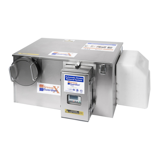
Grease Guardian X Series The FM Environmental Grease Guardian X series automatic grease removal unit (GRU) is a totally engineered system for separating free floating grease and oils from drain water flows. The separated grease and oils are trapped within the stainless steel tank and are automati- cally recovered by the system. -
Page 5: Dimensions & Specifications
Product Dimensions and Specification 230VAC FRONT VIEW TOP VIEW SIDE VIEW INLET END STRAINER BASKET REMOVAL CLEARANCE INLET INVERT Main Electrical Features OUTLET Motor 25 Watt, 230VAC, 50Hz, INVERT (all models) X7-X15: 600W/230VAC, with Thermal cut-out Heater X25-X35: 1000W/230VAC, with Thermal cut-out Time Control Logic Controller:, Backlit display (all models) - Page 6 Product Dimensions and Specification 110 VAC FRONT VIEW TOP VIEW SIDE VIEW INLET END STRAINER BASKET REMOVAL CLEARANCE INLET CENTER Main Electrical Features Motor 25 Watt, 110VAC, 60Hz, (all models) OUTLET CENTER 600W, 110VAC with Thermal cut-out Heater (all models) Time Control Logic Controller:, Backlit display (all models)
-
Page 7: Plumbing And Mechanical Installation
The Grease Guardian includes quick connect rubber couplings and blank- ing caps. Note that the fixtures pipe can enter the Grease Guardian inlet from left or right. (above rear view shows from right) If multiple pipes are being plumbed from opposite directions, under normal plumbing codes these must all combine to enter via one pipe via one direction only and should not be plumbed from both directions. - Page 8 - pipe diameter must be minimally of 2 inch diametre (50mm) - pipe must be installed at a gravity fall of 1:10 minimally, but preferably 1:40. - pipe must contain no more than 2 x 90 degree pipe bends between Grease Guardian outlet and final waste point in floor.
- Page 9 Plumbing and Mechanical Installation GREASE GUARDIAN “X” EXTERIOR FITTINGS Upgrade item Upgrade item Solids Strainer basket. Ensure there is adequate clearance to access and re- move the strainer as shown in the “Dimensions and specifications” page Manual spray bar valve and hose assembly 230VAC models only.
- Page 10 X25, X35 this system is only available as an upgrade at time of order. Wash water supply required:1/2 inch BSP, 0.75 l/ sec (0.2 USG/sec) @ 3-6 bar. Temp 40-60 C (104 - 140 F) The solenoid power cable is routed to Grease Guardian controller, and is pre- fitted at factory.
-
Page 11: Electrical Installation
Electrical Installation IMPORTANT: Grease Guardian Electrical Installation 1; Any engineer installing this product or its electrical supply circuit, must have the requisite qualification to do so according to the country of installation regulatory requirements, and must work to the appropriate Electrical codes of practice for that country. (ie, for the UK, the latest edition of BS7671. - Page 12 • Do not use highly acidic or highly alkaline detergents in ovens connected to Grease Guardian. • Do not flush or clean the Grease Guardian tank with bleach or any aggressive cleaners while the unit is in place. (The unit must be disconnected from the sinks before cleaning with these detergents.
-
Page 13: Controller Settings
Grease Guardian Controller: Cycle Programming Intro. Note on adjusting Hr/Min/Sec values on PLC: For PLC timer values that display a blinking icon, these can be adjusted by using the following button sequence: 1/ Press “-” or “+” to move the bar from one value to the next. - Page 14 Grease Guardian Controller: Cycle Programming Advanced notification will display for any weekday unit off tomorrow which is set to OFF. Displays during the inactive weekday, if a weekday is Inactive today set to OFF as described in the weekday display below.
- Page 15 Grease Guardian Controller: Cycle Programming Screen 1 Setting a Cycle. Choose a Skim Mode. (Screen 3) Screen 3 optimises the cycle duration Low Skim = 10 mins skimming/cycle DEFAULT Medium Skim = 20 mins skimming/cycle High Skim = 30 mins skimming/cycle Select a mode by pressing ...
- Page 16 Grease Guardian Controller: Cycle Programming Setting a Cycle. Spray Bar (Screen 6) The spray-bar is set to "ACTIVE" by default. It can be switched OFF ("INACTIVE") by toggling the "B" but- ton. The spray bar only runs during the grease skim- ming phase .
-
Page 17: Daily Maintenance
User Maintenance Daily Maintenance, 1-2 times daily Attention: Ensure sinks are emptied before accessing strainer basket! Before removing the strainer shake off Remove the strainer cap by rotating it 1/4 excess water by twisting it while it is still turn counter clockwise, using the hand grips. inside the tank. -
Page 18: Quarterly Clean Out
Pump outs ensure long-term performance and comply with our warranty terms. Pump outs must be carried out by a licenced catering waste collec- tor. After first disconnecting the Grease Guardian mains plug, tasks should include the following: Essential: ◼Tank pump out - all waste and liquid contents ◼Wipe clean of any debris from heater element. -
Page 19: Troubleshooting
If the grease appears hard or crusted, firstly try increasing the heater’s pre-heat time as advised in the controller pages section of this manual. Should this have no effect the Grease Guardian heater may require inspection by ser- vice engineer and possible replacement. - Page 20 Inlet pipe ventilation: Ventilation Tee and branch pipe. To prevent odors/odours escaping from the Grease Guardian into kitchen area the ventilation pipe should be terminated at the building’s stack vent with the outlet ventilation as below. If ventilating is not possible then alternatively the pump out frequency will need to be increased to control and reduce waste odors/odours.
- Page 21 Also seek to prevent any non- skimmable waste from entering the unit as already advised earlier. Scrape visible plate waste to bin rather than rinsing this waste into the Grease Guardian. Stagnant Water For applications where a connected sink or oven has a very low flow ensure to flush the Grease Guardian unit with fresh water regularly to reduce stagnant water.
-
Page 22: Parts Explosions
Parts Explosion X7 to X35. Basic Parts 1_Rubber Tank Coupler 2_Blanking rubber Cap 3_Cable gland 4_Wiper blade Assembly 5_Oil/Grease Container 6_Plastic Wiper blade 7_Gearbox 8_Drive Motor 9_Lid Switch 10_PLC controller 11_Control Panel Front Cover 12_Pushfit Connector Blocks 13_Motor Capacitor 14_ Strainer Cap Grip 15_Strainer Cap Plate 16_Strainer Cap 17_Solids Strainer... - Page 23 Parts Explosion. Wash Systems. External Fittings...
-
Page 26: Warranty Terms
1YEAR. a) The warranty period commences from the invoice date of the Grease Guardian product sale. b) All warranty claims must be processed through the Dealer from whom the equipment was purchased. - Page 27 GREASE GUARDIAN STAINLESS STEEL TANK FM Environmental Ltd warrants, to the original user, that the Grease Guardian main tank sup- plied and used in the service and in the manner for which it is intended shall be free from de- fects in materials and workmanship for a period of 10 YEARS.
- Page 28 10 YEAR ANTI - PERFORATION WARRANTY CONTINUED: The warranty is also void in following instances: • Detergents poured directly into the tank or in high concentrations. The use of bleach (chlorine) and aggressive chemicals when poured in sinks and fixtures discharging into the Grease Guard- ian is to be limited, and the tank is to be flushed with running tap water for a minimum duration of 5 minutes after these are used in the sinks so to dilute their effect.
Need help?
Do you have a question about the X Series and is the answer not in the manual?
Questions and answers