
Summary of Contents for ComNav G3
- Page 1 G3 GPS Compass G3 GPS Compass Display Installation & Installation & Operation Manual COMPLIES WITH CE REGULATIONS PN 29010092...
-
Page 3: Installation & Operation Manual
Congratulations on your purchase of ComNav Marine’s G3 GPS Compass Display! At ComNav, we are proud of our prominence as a leader in the design and manufacture of marine autopilot systems. Our dedication to performance and reliability will ensure your satisfaction with the G3 GPS Compass. -
Page 4: Document History
Add descriptions for IMO installation 03-24-2014 Add GNSS IMO Installation 10-04-2014 Correct screen samples 01-09-2017 Add description to NMEA 2000 alert monitoring 01-13-2017 Revise the alert view screenshot. Add ComNav alarm ID table Document PN 29010092 V2.3 - 2 -... -
Page 5: Table Of Contents
Table of Contents ............................3 List of Figures .............................. 5 List of Tables ..............................5 1 Installation ..............................7 1.1 G3 Compass Display Package Contents ______________________________________________________ 7 1.2 Planning _______________________________________________________________________________ 7 Maximum drop cable length _________________________________________________________________ 7 Current load and maximum nodes ____________________________________________________________ 7 Terminator resistor and position ______________________________________________________________ 7 1.3 Mounting ______________________________________________________________________________ 7... - Page 6 Appendix 1 – Tables of NMEA 2000 Parameter Group Numbers _____________________________________ 29 Appendix 2 – Abbreviations used in the screens __________________________________________________ 30 Appendix 3 – G3 GPS IMO Installation _________________________________________________________ 32 G3 Compass Display with G2/G2B __________________________________________________________ 32 Warranty Information ..........................38 User Notes ..............................
-
Page 7: List Of Figures
Figure 27 - IMO installation block diagram ........................33 Figure 28 – G2 IMO wiring diagram ..........................34 Figure 29 - G3 connection to NMEA 0183 Vector GPS compass ................35 Figure 30- Vector G2 IMO Wiring ..........................36 List of Tables Table 1 –... - Page 8 ComNav G3 GPS Compass Installation & Operation Installation Document PN 29010092 V2.3 - 6 -...
-
Page 9: Installation
G3 is designed for surface mount. It can drop in to a place where ComNav G3 Display was mounted. When you chose a place for G3, make sure you have at least 45 mm clearance at the back for the cable connector and its cover. Mounting template is shown on Figure 1. -
Page 10: Connecting To Nmea 2000 Network
If you already have a NMEA 2000 network on your boat, connecting your G3 Display to the network is easy. Finding a drop point tap that is within the distance of its length, the G3 Display Document PN 29010092 V2.3... -
Page 11: Connecting To Gps With Nmea 2000 Interface
Power supply and cable – NMEA 2000 network requires a dedicated power supply. The source is connected to the network bus at any drop point, just like the G3 Display and G2 GPS. You can purchase an NMEA 2000 power cable from ComNav. -
Page 12: Connecting To Vector Gps With Nmea 0183 Interface
2000 network, you need a NMEA 2000 to NMEA 0183 converter to connect the GPS and G3. Figure 27 shows where the converter is added. Note: If you are installing your G2 GPS with G3 in an IMO class boat, you need to follow the installation in Appendix 3 – G3 GPS IMO Installation. -
Page 13: Getting Start
Keep in mind that when you turn off your G3, you only switch off the display not the transducers that when you turn off your G3, you only switch off the display not the transducers that when you turn off your G3, you only switch off the display not the transducers the display associated with. - Page 14 ComNav G3 GPS Compass Installation & Operation Operation Document PN 29010092 V2.3 - 12 -...
-
Page 15: Operation
2.1 Keypad operation Keypad Home function G3 Display has 5 buttons. Each button is labeled by its home function. The home function is G3 Display has 5 buttons. Each button is labeled by its home function. The home function is G3 Display has 5 buttons. -
Page 16: Display
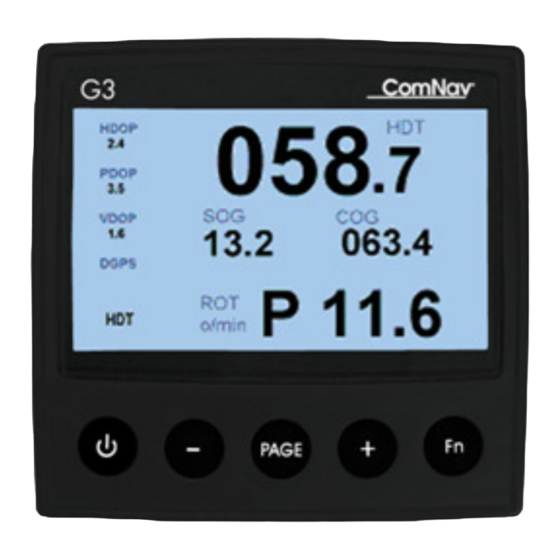
2.2 Display Display screens G3 is specifically designed to work with GPS compass. It has 15 predefined screens to show many kinds of GPS data. Press PAGE button you can scroll over these screens. A screen page is made up by several data fields. Typically, a data field has 3 visual components: the Name as the description of the data field, the Unit of the data, and the Value of the data. -
Page 17: Name As The Indicator Of Data Source
The Name in Figure 8 not only tells the meaning of the data of the field; it is also the indicator of the data source for this field. G3 uses the same data source for a data type across screens (Pages). -
Page 18: Screen Layouts
ComNav G3 GPS Compass Installation & Operation 2.3 Screen Layouts Large Compass Layout This layout is designed to show heading on a compass rose. The top of the rose points to the direction of heading from PGN 127250, with digital readout in the center of the rose. A second point (in yellow) points to the course-over-ground if that data is available. -
Page 19: Date And Time
ComNav G3 GPS Compass Installation & Operation Figure 13 - Satellites in View screen Date and Time This layout shows the universal time. Figure 14 – Date and Time screen Rate of Turn This layout presents the rate of turn in a scaled bar to give an easy visual display for the rate of turn of the vessel the GPS mounted on. -
Page 20: Digital Display
ComNav G3 GPS Compass Installation & Operation Figure 16 – Position screen Digital Display Digital screen layout can be in one field, two fields, three fields, four fields. In this layout data fields are presented in digits along with their label and unit. -
Page 21: Magnetic Heading Or True Heading
ComNav G3 GPS Compass Installation & Operation Main Menu Descriptions & options Settings … Backlight Level of 1, 2, 3, 4 Backlight Display mode in Blue, Green, Black, Night Display Units … Date format from yymmdd, mmddyy, ddmmyy Date Format... -
Page 22: Entering A Number Or Texts
1 and button 3 to enter “3”, and then press button 2 and button 1 for “6”. To finish the operation, you press button 4 and 5 as “Enter”. Once Enter or Cancel is received, G3 goes back to the Main menu. -
Page 23: Change Data Sources
After Assign Devices … is selected, G3 searches for all the NMEA 2000 devices. Then it lists all data G3 may monitoring on the left and all available devices on the right of the screen. Using “+” & “-“ buttons you can scroll over the data list and select one. Once a data item is selected, the cursor moves to the device list for you to pick the one you want for the selected data. -
Page 24: Reset To Factory Default
ComNav G3 GPS Compass Installation & Operation Figure 22 – Assign a device for a PGN Reset to factory default Factory default menu allows you to set all configurable parameters to the values as you first bought it. Acknowledge an alarm When an alert condition is triggered, and the alert view shows up on the screen, you can see “Ack. -
Page 25: Advance Operations
In Advance menu, when you Select Change PGN Rates, G3 will search for all devices in the network and show them in a list. Highlight the device you are interesting on, and Select it, G3 will request the transmitting PGN list from that device, and show it on the screen. This is illustrated in Figure 25. -
Page 26: Figure 26 - Screens During Setting Pgn Rates
ComNav G3 GPS Compass Installation & Operation Figure 26 - Screens during setting PGN rates Document PN 29010092 V2.3 - 24 -... - Page 27 ComNav G3 GPS Compass Installation & Operation Care & Maintenance Document PN 29010092 V2.3 - 25 -...
-
Page 28: Care And Maintenance
ComNav G3 GPS Compass Installation & Operation 3 Care and Maintenance The G3 display has been designed to provide many years of reliable service. The following periodic care and maintenance will help to ensure the longevity of your device. Cleaning and appearance The display unit should be carefully cleaned with a damp cloth and mild soap. - Page 29 ComNav G3 GPS Compass Installation & Operation Technical Specifications Document PN 29010092 V2.3 - 27 -...
-
Page 30: Technical Specifications
ComNav G3 GPS Compass Installation & Operation 4 Technical Specifications Model: Display: 4.3” Color TFT-LCD Resolution: 480 x 272 Viewing angles Horizontal 80° from each side Vertical 80° from above, 60° from below Backlight: white LED Dimensions: 120mm x 110mm Weight: 0.36Kg (0.8lb) -
Page 31: Appendix
ComNav G3 GPS Compass Installation & Operation Appendix Appendix 1 – Tables of NMEA 2000 Parameter Group Numbers PGN # PGN Name 059392 ISO acknowledgement 059904 ISO request 060928 ISO address claim 126996 NMEA Product information Table 3 – List of protocol and response-at-request PGNs... -
Page 32: Appendix 2 - Abbreviations Used In The Screens
ComNav G3 GPS Compass Installation & Operation Appendices Appendix 2 – Abbreviations used in the screens Abbreviation Description Vessel heading Course over ground Course to steer Rate of turn Speed over ground Speed, water referenced Satellites in view Latitude Longitude... -
Page 33: Table 6 - List Of Abbreviations For Units
ComNav G3 GPS Compass Installation & Operation Appendices Abbreviation Description ° M Degrees, magnetic for Heading, Course-over-ground, Course-to- steer ° T Degrees, true for Heading, Course-over-ground, Course-to-steer Nautical miles per hour Km/h Kilometers per hour ° /min Degree per minutes... -
Page 34: Appendix 3 - G3 Gps Imo Installation
IMO compliant status. G3 Compass Display with G2/G2B Accessories requirements To install your G2 GPS with G3 in a NMEA 0183 environment, your G2 cable must support G3 interface. Check that you have G2-CAN connection accessories (Table 6) in your package. -
Page 35: Figure 27 - Imo Installation Block Diagram
Appendices System Interconnections A basic G3 GPS Compass has one G2 GPS and one G3 Display. The CAN connection cable (PN 31110058) and G2 IMO Cable are provided with free leads, allowing easy in-field installation. Typically you will have other NMEA 0183 devices such as a navigator plotter or radar that will use the data from G2. -
Page 36: Figure 28 - G2 Imo Wiring Diagram
ComNav G3 GPS Compass Installation & Operation Appendices GNSS Cable Color Code Group Signal Net Wire Color CAN_H White CAN_L Blue NET_C Pink/Black NET_S Pink POWER BATT NEG Black BATT POS DRAIN Bare PORT 1 TX RS232 Brown PORT 1 RX RS232... -
Page 37: Figure 29 - G3 Connection To Nmea 0183 Vector Gps Compass
ComNav G3 GPS Compass Installation & Operation Installation & Operation Appendices Figure Figure 29 - G3 connection to NMEA 0183 Vector GPS compass GPS compass Document PN 29010092 V2.3 - 35 -... -
Page 38: Figure 30- Vector G2 Imo Wiring
ComNav G3 GPS Compass Installation & Operation Installation & Operation Appendices Figure 30- Vector G2 IMO Wiring Document PN 29010092 V2.3 - 36 -... - Page 39 ComNav G3 GPS Compass Installation & Operation Appendices Warranty Document PN 29010092 V2.3 - 37 -...
-
Page 40: Warranty Information
Improper or inadequate ancillary or connected equipment. OTHER LIMITATIONS AND EXCLUSIONS 1. ComNav does not warrant or guarantee the precision or accuracy of positions, heading, or other GPS-based navigation data obtained when using the Equipment. The potential accuracy of the Equipment, as stated in the Manual, associated ComNav literature and/or... - Page 41 The Limited Warranty will not apply with respect to any defective Equipment unless written notice of such defect is given to ComNav, by mail to the address for ComNav set forth below, or by facsimile to ComNav at 604-207-8008, and unless that written notice is received by ComNav within ten (10) days of the date upon which the defect first became known to the Purchaser.
- Page 42 Equipment, the place of purchase, the name and address of the installer, and the Purchaser’s name, address and telephone number, all to be sent, along with proof of purchase, to ComNav at the address set out below, and within the time limits set out above for Notice of Defect.
- Page 43 ComNav G3 GPS Compass Installation & Operation WARNING The Equipment is an aid to navigation only. It is not intended or designed to replace the person on watch. A qualified person should always be in a position to monitor the vessel’s heading, and to watch...
- Page 44 ComNav G3 GPS Compass Installation & Operation User Notes Document PN 29010092 V2.3 - 42 -...
-
Page 45: User Notes
User Notes ComNav G3 GPS Compass Installation & Operation User Notes Table 8 – User Notes Document PN 29010092 V2.3 - 43 -...
Need help?
Do you have a question about the G3 and is the answer not in the manual?
Questions and answers