Table of Contents
Advertisement
USE AND
USE
USE
USE AND
MAINTENANCE MANUAL
MAINTENANCE MANUAL
MAINTENANCE MANUAL
MAINTENANCE MANUAL
BRAVE 30 ES
BRAVE 30 ES
BRAVE 30 ES
BRAVE 30 ES
Celli S.p.A.
Via Casino Albini, 605
47842 - S. Giovanni in Marignano - Rimini - Italy
Tel. +39 0541 755211 - Fax +39 0541 759735
www.celli.com - celli@celli.com
AND
AND
BRAVE 90 ES
BRAVE 90 ES
BRAVE 90 ES
BRAVE 90 ES
BRAVE 60 ES
BRAVE 60 ES
BRAVE 60 ES
BRAVE 60 ES
TRANSLATION OF THE ORIGINAL
ED. 10
30/10/2017
Code 070344
Advertisement
Table of Contents

Summary of Contents for Celli Brave 30 ES
- Page 1 USE AND USE AND MAINTENANCE MANUAL MAINTENANCE MANUAL MAINTENANCE MANUAL MAINTENANCE MANUAL BRAVE 30 ES BRAVE 30 ES BRAVE 60 ES BRAVE 60 ES BRAVE 30 ES BRAVE 30 ES BRAVE 60 ES BRAVE 60 ES BRAVE 90 ES BRAVE 90 ES...
-
Page 3: Table Of Contents
Index Brave 30 ES - Brave 60 ES- Brave 90 ES Index 1 - Safety ........................3 Intended use ........................3 Improper use ........................3 List of hazards ........................4 Residual risks ........................6 2 - General information ....................7 Manufacturer’s details ...................... - Page 4 Index Brave 30 ES - Brave 60 ES - Brave 90 ES 5 - Using the machine ....................42 Start-up........................... 42 Stopping the machine ....................... 42 6 - Maintenance......................43 Routine maintenance ......................43 Table of procedures......................44 Replacing the syrup tank....................45 6.3.1 Replacing a steel keg ....................
-
Page 5: Safety
Safety Brave 30 ES- Brave 60 ES - Brave 90 ES 1 - Safety Do not allow anyone to operate the machine unless suitably trained. Keep the machine in good working order and do not allow any modifications to it unless these have been authorised by the manufacturer. -
Page 6: List Of Hazards
Safety Brave 30 ES - Brave 60 ES - Brave 90 ES List of hazards The following list of hazards details the safety factors which the appliance users must bear in mind. DANGER (CARBON DIOXIDE) The place where the CO cylinders are stored must always be well ventilated, with an air flow inlet and outlet. - Page 7 Safety Brave 30 ES- Brave 60 ES - Brave 90 ES WARNING AUTHORISED TECHNICAL STAFF Only technical staff who are skilled electricians or plumbers, or with expertise in cooling systems, may carry out work on the machine. All wiring and plumbing components must comply with national and local legal requirements (when replacing components, use only genuine parts certified by CELLI S.p.A.).
-
Page 8: Residual Risks
Safety Brave 30 ES - Brave 60 ES - Brave 90 ES Residual risks During regular operating conditions the machine is safe. There are still residual risks, listed in the hazard list, which are reduced if the machine is used correctly and according to the instructions given in the user’s manual. -
Page 9: General Information
CELLI S.p.A. is at users' service for any technical problems, and for the supply of spare parts. When replacing parts of the appliance, genuine parts must be used. The manufacturer declines all responsibility for any deterioration in the appliance's performance or damage caused to it due to the use of non-genuine parts. -
Page 10: Machinery Identification
It contains the model, the serial number and all the machine technical data necessary for ordering spare parts or reporting technical problems to the service centre. Warranty For the warranty terms, please refer to the general conditions of sale in the CELLI S.p.A. price list. Rev. 10/17... -
Page 11: Symbols Used In The Manual
General information Brave 30 ES- Brave 60 ES - Brave 90 ES Symbols used in the manual The manual uses the following safety symbols to draw readers' attention to all operations which must be strictly observed in order to prevent injury to persons or damage to the appliance. -
Page 12: Description Of The Machine
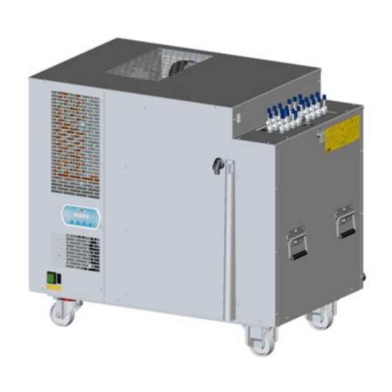
Description of the machine Brave 30 ES - Brave 60 ES - Brave 90 ES 3 - Description of the machine The machines of the BRAVE ES range (models 30 - 60 - 90) are coolers that dispense sparkling and non- sparkling drinks, obtained by mixing water and syrups. -
Page 13: Main Components Of The Brave 30 Es
Description of the machine Brave 30 ES- Brave 60 ES - Brave 90 ES Main components of the BRAVE 30 ES BR0020... - Page 14 Description of the machine Brave 30 ES - Brave 60 ES - Brave 90 ES UPPER COVER STIRRER CARBONATOR SYRUP COILS STILL WATER COIL SODA COIL SODA RECIRCULATION COIL EVAPORATOR INSULATING TANK CONDENSERS FOR THE STIRRER AND PUMP MOTORS 10 -...
-
Page 15: Main Components Of The Brave 60 Es
Description of the machine Brave 30 ES- Brave 60 ES - Brave 90 ES Main components of the BRAVE 60 ES BR0030... - Page 16 Description of the machine Brave 30 ES - Brave 60 ES - Brave 90 ES UPPER COVER STIRRER CARBONATOR SYRUP COILS STILL WATER COIL SODA COIL SODA RECIRCULATION COIL EVAPORATOR INSULATING TANK CONDENSERS FOR THE STIRRER AND PUMP MOTORS 10 -...
-
Page 17: Main Components Of The Brave 90 Es
Description of the machine Brave 30 ES- Brave 60 ES - Brave 90 ES Main components of the BRAVE 90 ES BR0040... - Page 18 Description of the machine Brave 30 ES - Brave 60 ES - Brave 90 ES UPPER COVER STIRRER CARBONATOR PRE-MIX COILS SODA RECIRCULATION COIL COIL FOR PRE-MIX + 4 SYRUPS COIL FOR SODA + 4 SYRUPS EVAPORATOR INSULATING TANK CONDENSERS FOR THE STIRRER AND PUMP MOTORS...
-
Page 19: Operating Principle
Description of the machine Brave 30 ES- Brave 60 ES - Brave 90 ES Operating principle The machine consists of a cooling unit and a hydraulic unit. The cooling unit cools the water in the insulating tank, thanks to an evaporator (A) immersed in the tank itself. - Page 20 Description of the machine Brave 30 ES - Brave 60 ES - Brave 90 ES Sparkling water (soda) When you make a dispensing request for sparkling water, the still water is pushed by the pump (D) into the carbonator (E); it comes into contact with the CO (carbon dioxide), absorbing it immediately and becoming sparkling.
- Page 21 Description of the machine Brave 30 ES- Brave 60 ES - Brave 90 ES Still water, with pressure switch and solenoid valve The machines that adopt this technical solution use the same pump for the carbonator and for the still water (see the electric and hydraulic diagrams for further details).
-
Page 22: Energy Saving Control Unit, And Button Pad With Display
The control unit has been configured for connection to a telemetry module (an optional service - contact CELLI SpA for more information) which allows the remote monitoring of machine functions and management of anomalies and alarms by optimising routine and special maintenance work. -
Page 23: Standard Functions
Description of the machine Brave 30 ES- Brave 60 ES - Brave 90 ES 3.5.1 Standard functions Carbonation pump button This button enables or disables operation of the carbonation pump. Still water pump button This button enables or disables operation of the still water dispensing pump. -
Page 24: Optional Functions
Description of the machine Brave 30 ES - Brave 60 ES - Brave 90 ES 3.5.2 Optional functions Compressor delivery tube temperature check This function allows you to monitor the compressor delivery temperature: if the safety limit is "HIGH TEMP COMPR exceeded, the warning message ”... - Page 25 Description of the machine Brave 30 ES- Brave 60 ES - Brave 90 ES functions are restored, and the message disappears as soon as the CO pressure returns within acceptable limits. The alarm is transmitted via telemetry, if present. Carbonation pump pressure check This function allows you to monitor the carbonation pump delivery pressure, to ensure it is operating "CARB P LOW PR...
- Page 26 BULK LEV LOW Inadequate mains voltage PROTEZ VOLTAGGIO Automatic VOLTAGE PROTECT Display language The display is factory-programmed in English (EN). You can visualise the display in Italian by altering the control unit programming parameters. Contact Celli for further details. Rev. 10/17...
-
Page 27: Technical Data
Description of the machine Brave 30 ES- Brave 60 ES - Brave 90 ES Technical data BRAVE 30 ES BRAVE 60 ES BRAVE 90 ES Body STAINLESS STEEL / STAINLESS STEEL / STAINLESS STEEL / AISI 430 AISI 430 AISI 430... -
Page 28: Dimensions In Mm
Description of the machine Brave 30 ES - Brave 60 ES - Brave 90 ES Dimensions in mm 3.7.1 BRAVE 30 ES 632 (24.8) 436 (17.1) 478 (18.8) BR0120 3.7.2 BRAVE 60 ES 722 (28.4) 491 (19.3) 566 (28.4) BR0130 3.7.3 BRAVE 90 ES... -
Page 29: Differential-Switch Power Cord (Optional)
Description of the machine Brave 30 ES- Brave 60 ES - Brave 90 ES Differential-switch power cord (optional) The differential switch is a safety device designed to cut off power to the machine in the event of a ground fault... -
Page 30: Installation
Installation Brave 30 ES - Brave 60 ES - Brave 90 ES 4 - Installation Checks and Unpacking Always check that the machine received corresponds to the model indicated in the accompanying document. The machine is shipped in a cardboard box. Once the packaging has been removed, check the machine has not been damaged in transit;... -
Page 31: Environmental Conditions
Installation Brave 30 ES- Brave 60 ES - Brave 90 ES Environmental conditions The machine must be positioned so it is protected from rain and water splashes, and in a location with the temperature appropriate to its climate class (stated on the EC nameplate); otherwise warranty rights are forfeited and malfunctions may occur. -
Page 32: Connections
Installation Brave 30 ES - Brave 60 ES - Brave 90 ES Connections Carry out the connections described with the machine switched off and the power cord unplugged. 4.5.1 Preparing the machine Overflow connection Use a tube to connect the overflow drainage connector... -
Page 33: Water Intake Connection
Installation Brave 30 ES- Brave 60 ES - Brave 90 ES 4.5.2 Water intake connection To facilitate the connections, the inlets and outlets are identified by special adhesives. WATER INTAKE IN/OUT ADHESIVE BR0210 BR00170 Use only food-approved tubes and fittings when connecting the machine to the water supply system. - Page 34 Installation Brave 30 ES - Brave 60 ES - Brave 90 ES EXAMPLE OF A CONNECTION TO THE WATER SUPPLY VIA THE FILTER DRINKING H PRESSURE REDUCER Ø i 9.5mm O IN CHECK VALVE IN COMPLIANCE WITH EN 61770 DRAINAGE (FOR...
-
Page 35: Connecting The Syrup Lines
Installation Brave 30 ES- Brave 60 ES - Brave 90 ES 4.5.3 Connecting the syrup lines To facilitate the connections, the inlets and outlets are identified by special adhesives. SYRUP INLET IN/OUT ADHESIVE BR0210 BR00173 The connection of the syrup lines differs according to whether the syrup is contained in a bag-in-box or in stainless steel kegs. -
Page 36: Connecting The Python
Installation Brave 30 ES - Brave 60 ES - Brave 90 ES 4.5.5 Connecting the python Connect the python to the dispensing tower (not included) with the soda recirculation line. When positioning the python, keep it away from heat sources, particularly tight bends, or any point where it may get crushed. -
Page 37: Carbon Dioxide
Installation Brave 30 ES- Brave 60 ES - Brave 90 ES 4.5.6 Carbon dioxide (CO ) connection To facilitate the connections, the inlets and outlets are identified by special adhesives. DANGER (CARBON DIOXIDE) The place where the CO cylinders are stored must always be well ventilated, with an air flow inlet and outlet. - Page 38 Installation Brave 30 ES - Brave 60 ES - Brave 90 ES LOW PRESSURE GAUGE LOW PRESSURE GAUGE WITH FULL SCALE WITH FULL SCALE 10 bar (145 psi - 1 MPa) 6 bar (87 psi - 0,6 MPa) VENT VALVE...
-
Page 39: Electrical Connection
Installation Brave 30 ES- Brave 60 ES - Brave 90 ES 4.5.7 Electrical connection CAUTION ELECTRICAL REQUISITES The electrical circuit must be correctly earthed and connected by means of a suitable differential safety breaker. CAUTION PLUG SUPPLIED Connect the machine to the electricity mains using the plug provided. -
Page 40: Adjusting The Carbon Dioxide (Co ) Supply
Installation Brave 30 ES - Brave 60 ES - Brave 90 ES Adjusting the carbon dioxide (CO ) supply 1 - Slowly open the valve of the CO cylinder until it is fully open. Check the gas cylinder pressure is always above the red segment (A - low level) of the pressure reducer pressure gauge;... -
Page 41: Checking For Leaks
Installation Brave 30 ES- Brave 60 ES - Brave 90 ES Checking for leaks 1 - Vent the air from the carbonator by opening the vent valve (B) until only water comes out. 2 - Check for gas leaks by pressurising the system and closing the gas cylinder valve. - Page 42 Installation Brave 30 ES - Brave 60 ES - Brave 90 ES Flow levels based on a ratio of 5:1 Drink g/s (oz/s) Water g/s (oz/s) Syrup g/s (oz/s) 42g/s (1.5oz/s) 35g/s (1.25oz/s) 7g/s (0.25oz/s) 56g/s (2oz/s) 47g/s (1.67oz/s) 9.4g/s (0.33oz/s) 70g/s (2.5oz/s)
-
Page 43: First Start-Up
Installation Brave 30 ES- Brave 60 ES - Brave 90 ES SYRUP ADJUSTER WATER FLOW SYRUP TAP SCREW REGULATOR WATER TAP SYRUP FLOW REGULATOR WATER ADJUSTER SCREW REFRACTOMETER MIXER SPOUT Clockwise to increase LIQUIDS SEPARATOR Anticlockwise to reduce BR0420 After making all the connections and adjustments, you must sanitise the syrup lines (chapter ”6.8” pag. 49). -
Page 44: Using The Machine
Using the machine Brave 30 ES - Brave 60 ES - Brave 90 ES 5 - Using the machine Start-up 1 - After checking that all the connections and adjustments are correct, connect the machine to the electricity supply by inserting the plug in the nearest suitable socket. -
Page 45: Maintenance
CELLI S.p.A. will consider itself relieved of any responsibility for people's safety or machine malfunctioning. -
Page 46: Table Of Procedures
Maintenance Brave 30 ES - Brave 60 ES - Brave 90 ES Table of procedures The table below details the maintenance procedures required at the stated intervals. These periods refer to normal conditions of use. Maintenance Check Table Operation required... -
Page 47: Replacing The Syrup Tank
Maintenance Brave 30 ES- Brave 60 ES - Brave 90 ES Replacing the syrup tank When the syrup runs out, replace the tank (steel keg or bag-in-box). To replace it, proceed as follows: 6.3.1 Replacing a steel keg CAUTION SYRUP CONTAINED IN PRESSURISED KEGS... -
Page 48: Replacing The Carbon Dioxide Cylinder (Co 2 )
Maintenance Brave 30 ES - Brave 60 ES - Brave 90 ES Replacing the carbon dioxide cylinder (CO When the needle of the reducer high pressure gauge is in the red segment, the cylinder needs replacing. 1 - Note down the pressure values set on the pressure reducer, then fully close the cylinder using its valve. -
Page 49: Replacing The Water Filter
Maintenance Brave 30 ES- Brave 60 ES - Brave 90 ES Replacing the water filter For the times and procedures for changing the water filter cartridge, follow the instructions provided by the filter manufacturer. After fitting or replacing the filter, allow the water to flow from the drain tap (just after the filter) until the water leaving the appliance is free from all cloudiness or sediment. -
Page 50: Cleaning The Condenser
Maintenance Brave 30 ES - Brave 60 ES - Brave 90 ES Cleaning the condenser The build-up of dust and grease on the cooling condenser may cause overheating, and this in turn could damage the compressor beyond repair. The condenser must always be cleaned when necessary. -
Page 51: Sanitising The Dispenser
Maintenance Brave 30 ES- Brave 60 ES - Brave 90 ES Sanitising the dispenser CAUTION SANITIZATION Before sanitizing the machine, carefully read the instructions given by the sanitization product manufacturer and put on all the necessary personal protective equipment (gloves, masks, etc.). - Page 52 Maintenance Brave 30 ES - Brave 60 ES - Brave 90 ES 14 - Dispense from the valve until the detergent solution begins to come out (typically after 15 seconds / 5 mt of python); open the valve for 15 sec and stop for 5 sec: repeat for 4 times, open the valve for 30 sec.
-
Page 53: Cleaning And Checking The Liquid Check Valve
Maintenance Brave 30 ES- Brave 60 ES - Brave 90 ES 15 - Reconnect the connector to the syrup container, and intervene on the dispensing valve until syrup begins to come out. 16 - Turn on the water tap on the dispensing valve again, and replace the cover. -
Page 54: Replacing The Water In The Tank
Maintenance Brave 30 ES - Brave 60 ES - Brave 90 ES 6.11 Replacing the water in the tank 1 - Disconnect the machine from the electricity supply. 2 - Remove the upper cover. 3 - Wait until the ice bank has fully melted. -
Page 55: Troubleshooting
Troubleshooting Brave 30 ES- Brave 60 ES - Brave 90 ES 7 - Troubleshooting PROBLEM PROBABLE CAUSE REMEDIES Power supply failure Check that power is present. If the power is OK, call an authorised The dispenser does not start up technician. -
Page 56: Additional Instructions
Additional instructions Brave 30 ES - Brave 60 ES - Brave 90 ES 8 - Additional instructions Waste disposal Please note that residues from industrial processing are to be considered special waste that, in terms of quality or quantity, are not intended as municipal waste. -
Page 57: Disposal Of Electronic Equipment (Weee Directive)
Additional instructions Brave 30 ES- Brave 60 ES - Brave 90 ES Disposal of electronic equipment (WEEE directive) The EU Directive 2002/96/EC (WEEE), requires manufacturers and users of electrical and electronic equipment a number of obligations relating to the collection, treatment, recovery and disposal of such waste. -
Page 58: Annexes
Annexes Brave 30 ES - Brave 60 ES - Brave 90 ES 9 - Annexes BRAVE 30-60 ES electrical diagram Version with still water and special pump 083639 BR0390 The electrical diagram can also be found on the inner part of the insulating tank cover. Refer to that diagram if there are any differences compared with the one above. -
Page 59: Brave 30-60 Es Electrical Diagram Version With Still Water
Annexes Brave 30 ES- Brave 60 ES - Brave 90 ES BRAVE 30-60 ES electrical diagram Version with still water BR0381 The electrical diagram can also be found on the inner part of the insulating tank cover. Refer to that diagram... -
Page 60: Brave 30-60 Es Electrical Diagram Version With Still Water And Telemetry
Annexes Brave 30 ES - Brave 60 ES - Brave 90 ES BRAVE 30-60 ES electrical diagram Version with still water and telemetry BR0430 The electrical diagram can also be found on the inner part of the insulating tank cover. Refer to that diagram if there are any differences compared with the one above. -
Page 61: Brave 90 Es Electrical Diagram Version With Still Water, Pressure Switch And Solenoid Valve
Annexes Brave 30 ES- Brave 60 ES - Brave 90 ES BRAVE 90 ES electrical diagram Version with still water, pressure switch and solenoid valve BR0380 The electrical diagram can also be found on the inner part of the insulating tank cover. Refer to that diagram... -
Page 62: Brave 90 Es Electrical Diagram Version With Still Water And Telemetry
Annexes Brave 30 ES - Brave 60 ES - Brave 90 ES BRAVE 90 ES electrical diagram Version with still water and telemetry BR0440 The electrical diagram can also be found on the inner part of the insulating tank cover. Refer to that diagram if there are any differences compared with the one above. -
Page 63: Brave Es Hydraulic Diagram Version With Special Still Water Pump
Annexes Brave 30 ES- Brave 60 ES - Brave 90 ES BRAVE ES hydraulic diagram Version with special still water pump BR0400... -
Page 64: Brave Es Hydraulic Diagram Version With Still Water Kit, Pressure Switch And Solenoid Valve
Annexes Brave 30 ES - Brave 60 ES - Brave 90 ES BRAVE ES hydraulic diagram Version with still water kit, pressure switch and solenoid valve BR0410 Rev. 10/17... -
Page 65: Brave 30 - 60 Es Hydraulic Diagram Version With Still Water And Telemetry
Annexes Brave 30 ES- Brave 60 ES - Brave 90 ES BRAVE 30 - 60 ES hydraulic diagram Version with still water and telemetry BR0402... -
Page 66: Brave 90 Es Hydraulic Diagram Version With Still Water/Carbonator
Annexes Brave 30 ES - Brave 60 ES - Brave 90 ES BRAVE 90 ES hydraulic diagram Version with still water/carbonator BR0402 Rev. 10/17... - Page 68 47842 - S. Giovanni in Marignano - Rimini - Italy Tel. +39 0541 755211 - Fax +39 0541 759735 www.celli.com - celli@celli.com WE RESERVE THE RIGHT TO MODIFY OUR PRODUCTS IN ANY WAY WE CONSIDER USEFUL, WITHOUT PREWARNING Rev. 10 30/10/2017 - Code 070344...