Advertisement
Quick Links
Advertisement

Summary of Contents for 3B SCIENTIFIC U192001
- Page 1 ® 3B SCIENTIFIC PHYSICS X-ray apparatus U192001 Instruction sheet 05/11 ALF / Hh...
- Page 2 Section 8.1. found, do not attempt to operate the equipment Never open the housing of the X-ray apparatus. Any but inform the manufacturer UK 3B Scientific Ltd. attempt to manipulate, repair or otherwise tamper • Please do not dispose of the packaging, since it with the equipment other than setting it up for use might be handy should you need to return the item.
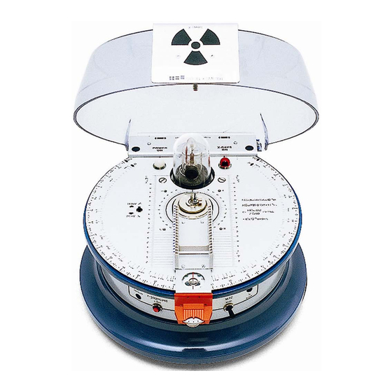
- Page 3 3. Components and control elements Fine adjustment trimmer for goniometer Timer Trimming potentiometer for setting emitter current Key switch for mains supply High voltage ON/OFF button giving Jack socket for emitter current measurement, Housing an output voltage proportional to current Base Cover 10 Screening plate with radiation warning label...
- Page 4 11 Dumbbell shaped slot for locking the cover 19 X-ray tube 12 Protractor scale for measuring arm 20 Access holes 13 Measuring arm with magazine for photographic 21 Leaded glass dome slides 22 Locking pin for cover 14 Pressure plate 23 Length scale for focal point 15 Protractor scale for sample holder 24 4-mm sockets for addition of driver motor...
- Page 5 28 Circuit breaker for mains supply 31 Ventilation grille 29 Circuit breaker for high voltage supply 32 Mains socket 30 Mains voltage selector switch rotation. The arm takes the form of a magazine for 4. Description photographic slides and can also accommodate a The X-ray apparatus allows you to undertake a wide Geiger-Müller counter (U19201), an ionisation cham- variety of experiments on the following topics:...
- Page 6 2. Basic equipment set U19205 5. Scope of delivery The basic equipment set allows for qualitative 1 Basic apparatus and quantitative experiments, e.g. on straight- 1 X-ray tube line propagation, ionisation, penetration by X- rays and X-ray photograph, demonstration of the 1 Jack plug wave nature of X-ray radiation, investigation of X- 2 Fuses...
- Page 7 half-value thickness (HVT); exposure times, non- 9. Geiger-Müller tube U19201 destructive material analysis. The Geiger-Müller counter tube is a self- Scope of delivery: quenching halogen-trigger counter tube for regis- tering α, β, γ and X radiation. Maltese cross Dose rate range: to 10²...
- Page 8 • 8.2.3 Closing the cover and switching on the high Check the locking pin of the cover for any dam- voltage age. • • Once the mains is connected, select the high Check that the leaded glass dome and brass collimator are free of damage and firmly se- voltage supply U = 20 kV/30 kV via the slide switch.
- Page 9 • • Read of the relative angle from the vernier (accu- Turn on the X-ray apparatus and select a high rate to about 5 minutes of arc). voltage of 20 kV. • Set the emitter current so that the counter tube 8.2.8 Angle coupling 2:1 registers around 200 to 400 pulses per second To photograph a Bragg spectrum the measuring arm...
- Page 10 • 9.6 Debye-Scherrer camera (from U19205) with Move the measuring arm to find a maximum for the reflex. If necessary, keep adjusting until the motor drive (U19202) measured and quoted values do lie within the The Debye-Scherrer camera is made up of three 30' tolerance.
-
Page 11: Troubleshooting
better if it is transferred to a smaller con Development Developer Fixer tainer. This means it remains usable for longer. Time 1½ min. 4 min. • Before closing the developer bottle, squeeze the Filmpack 2 2½ ml 3½ ml bottle so that the fluid comes to brim before closing it. - Page 12 High voltage indicator light is not Safety circuit Check the safety circuit as specified working even though the mains in Section 8.1, especially the fas- tening of the leaded glass dome indicator is on and the hinges and locking of the cover.
- Page 13 Fig. 1 Inserting the fluorescent screen onto the measuring arm Fig. 2 Inserting the ionisation chamber onto the measuring arm Fig. 3 Inserting the Geiger-Müller tube onto the measuring arm Fig. 4 Geometry of Bragg reflections (a. X-ray tube, b. Monocrystal, c. Counter tube)
- Page 14 Fig. 5 Insertion of crystal into sample holder (a Screw, b Clamp, c Base, d Fixed section of sample holder) Fig. 6 Assembly of ionisation chamber (A for low pressure, B for normal atmospheric pressure) Fig. 7 Insertion and removal of Debye-Scherrer camera...
- Page 15 Fig. 9 Insertion of scattering film revolver magazine A TELTRON Product from UK3B Scientific Ltd. • 8 Beaconsfield Road • Weston-super-Mare • Somerset BS23 1YE Tel 0044 (0)1934 425333 • Fax 0044 (0)1934 425334 • e-mail uk3bs@3bscientific.com Subject to technical amendments © Copyright 2008 3B Scientific GmbH...
Need help?
Do you have a question about the U192001 and is the answer not in the manual?
Questions and answers