
Related Manuals for weed instrument Head Mount Sensor Mate 4500H

Summary of Contents for weed instrument Head Mount Sensor Mate 4500H
- Page 1 Model 4500H BA 163R/24/ae/05.04 ® Head Mount Sensor Mate PC programmable RTD Temperature Transmitter Operating instructions...
- Page 2 Model 4500H Safety message Instructions and procedures in the operating instructions may require special precau- tions to ensure the safety of the personnel performing the operations. Information that potentially raises safety issues is indicated by safety pictograms and symbols. Please refer to the safety messages before performing an operation preceded by pictograms and symbols, see chapter 1.4.
-
Page 3: Table Of Contents
Model 4500H Weed Table of contents Safety notes ....4 Designated use ......4 Installation, commissioning and operation . -
Page 4: Safety Notes
Safety notes Model 4500H Safety notes Safe and secure operation of the head transmitter can only be guaranteed if the operating instructions and all safety notes are read, understood and followed. Designated use • The unit is a presettable temperature head transmitter for resistance temperature detectors (RTD). -
Page 5: Safety Pictograms And Symbols
Model 4500H Identification Safety pictograms and symbols Safe and reliable operation of this unit can only be guaranteed if the safety notes and warnings in these operating instructions are followed. The safety notes in these instructions are highlighted using the following symbols. Note! This icon indicates activities and actions that, if not followed correctly, could have an indirect influence on the unit operation or could lead to an unforeseen unit reaction. -
Page 6: Installation
Installation Model 4500H Installation Installation condition When installing and operating the unit, please take note of the allowable ambient temperature (see chapter 10 "Technical Data"). 3.1.1 Dimensions The head transmitter dimensions can be found in chapter 10 "Technical data". 3.1.2 Installation point •... -
Page 7: Installation
Model 4500H Installation Installation 3.2.1 Typical installation Industrial thermocouple or RTD assembly with head transmitter (see Fig. 1) • Attach the thermowell (Pos. 1) to the pipe or process container wall. Install and tighten thermowells before applying process pressure. • Attach necessary extension nipples and adapters (Pos. 3) to the thermowell. Seal the nipple and adapter threads with teflon tape. -
Page 8: Wiring
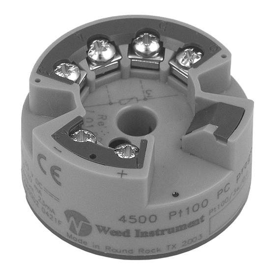
Wiring Model 4500H Wiring Overview Terminal layout Fig. 2: Head transmitter wiring Measurement unit connection " Caution! • Switch off power supply before opening the housing cover. Do not install or connect the unit to power supply. If this is not followed parts of the electronic circuit will be damaged. -
Page 9: Potential Grounding
Model 4500H Wiring Note! The screws on the terminals must be screwed in tightly. Configuration during measurement operation is possible. There is no need to disconnect cables! Potential grounding Note! Please take note of the following when remotely installing the head transmitter in a field housing. -
Page 10: Operation
Operation Model 4500H Operation Communication The transmitter must be set up using a PC and configuration set. The following points must be taken into account if trouble-free setup is to be achieved: • Configuration software installation • Connect the transmitter to the PC using the connection cable from the configuration set. -
Page 11: Commissioning
Model 4500H Commissioning Commissioning Installation and function check Installation check Monitor all connections making sure they are tight. In order to guarantee fault-free operation, the terminal screws must be screwed tightly onto the connection cables. Function check Measuring the analog 4 to 20 mA output signal or following failure signals: Measurement range undercut linear fall to 3.8 mA Measurement range excess... - Page 12 Commissioning Model 4500H Configurable parameters (Default settings in bold) Standard settings Sensor type Sensor type Range start value Range end value min. range Pt100 -328 °F (-200 °C) 1202 °F (650 °C) 18 °F (10 °C) Pt100 -58 °F (-50 °C) 482 °F (250 °C) 18 °F (10 °C) Polynom RTD...
-
Page 13: Maintenance
Model 4500H Maintenance Configurable parameters (Default settings in bold) Service functions Output Activate simulation mode. Input: simulation • • Input of the simulation value (current). Input: 3.8 to 20.5 mA Customer-specific linearization Customer-specific linearization and sensor matching are activated after the POLYNOM RTD sensor type is selected. -
Page 14: Application Errors Without Messages
Trouble-shooting Model 4500H Application errors without messages 9.2.1 General application errors Error Cause Action/cure 2 wire connection incorrect Re-connect correctly (see connection diagram) No power supply on the 2-wire Check the current loop connection No communication Power supply too low (< 10 V) Check power supply Defective interface cable Check interface cable... -
Page 15: Technical Data
Model 4500H Technical Data Technical Data 10.0.1 Function and system design Measuring principle Electronic monitoring and conversion of input signals in industrial temperature measurement. Measuring system The temperature transmitter is a two wire transmitter with an analog output. It has measurement input for resistance temperature detectors (RTD) in 2-, 3- or 4-wire connection. - Page 16 Technical Data Model 4500H Source impedance max. (V - 10 V) / 0.022 A (current Power supply output) e.g. (24 V - 10 V)/0.022 A = 636.4 Ω Transmission behavior Temperature linear Filter 1st order digital filter: 0 to 8 s ≤...
- Page 17 Model 4500H Technical Data • Resistance thermometer Pt100: Influence of ambient temperature (Temperature = ±(8.3 ppm/°F * (full scale point or 20 mA temperature + 328) + 27.8 ppm/°F * span) * ∆ ϑ drift) ∆ ∆ ∆ ∆ ϑ ϑ ϑ ϑ Deviation of the ambient temperature according to the reference condition (73.4 °F ±...
- Page 18 Technical Data Model 4500H Electromagnetic CE Electromagnetic Compatibility Compliance compatibility (EMC) The device meets all requirements listed under IEC 61326 Amendment 1, 1998 This recommendation is a uniform and practical way of determining whether the devices used in laboratory and process control are immune to interference with an objective to increase its functional safety.
- Page 19 Model 4500H Technical Data • IEC 60529: Other standards and guidelines Degrees of protection by housing (IP-Code) • IEC 61010: Safety requirements for electrical measurement, control and laboratory instrumentation • IEC 61326: Electromagnetic compatibility (EMC requirements) • NAMUR Standardization association for measurement and control in chemical and pharmaceutical industries.
-
Page 20: Index
Model 4500H Weed Index Brief overview ....... 2 CE mark........5 Configuration software documentation . - Page 22 For Weed Instrument contact call 1 800 880 9333 Internet: www.weedinstrument.com BA 163R/24/ae/05.04 FM+SGML6.0 ProMoDo...
Need help?
Do you have a question about the Head Mount Sensor Mate 4500H and is the answer not in the manual?
Questions and answers