Table of Contents
Advertisement
Quick Links
Advertisement
Table of Contents

Related Manuals for Rinnai N-BW2


Summary of Contents for Rinnai N-BW2
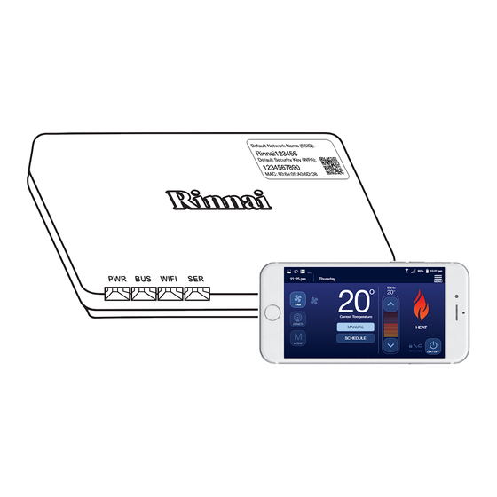
- Page 1 Rinnai Touch Wi-Fi Kit N-BW2 Installation Manual 10:21 pm WIFI 11 :25 pm Thursday MENU Set to Current Temperature ZONES MANUAL HEAT SCHEDULE MODE Temporary ON / OFF APPLY MODULE IDENTIFICATION LABEL HOME OWNER TO RETAIN FOR FUTURE REFERENCE...
- Page 3 The Terms and Conditions are available when downloading the While the supply of the information is voluntary, if our customers Rinnai Touch App used to connect with the Wi-Fi Module. Please cannot, or do not wish to provide the information sought, the read these carefully before proceeding.
- Page 4 Access Point Home Direct MTSP Multi-Temperature Set Point In this state the N-BW2 Wi-Fi Module operates as an access point STSP Single Temperature Set Point which can be associated with the SSID and WPA passphrase N-PM1 Zone Plus Power Module defined by the user.
- Page 5 It may also be used to alert against unsafe practices. WARNING. The Rinnai Touch Wi-Fi Module is supplied with a 12V DC Plug Pack Socket if required. Only this power supply must WARNING be used.
-
Page 6: Table Of Contents
Compatibility and Requirements ........7 Specifications ...............7 Module Overview Pre-Installation Installation Wi-Fi Module Location ..........10 Securing the Wi-Fi Module ........11 Electrical Control Wiring ..........11 Wi-Fi Module Unique Identification Labels Powering On Wi-Fi Module Error Codes Rinnai Touch Wi-Fi Kit IM... -
Page 7: Hardware Installation
Location: Wi-Fi Module shall be within 10m of wireless router where applicable. COMPATIBILITY AND REQUIREMENTS Product Compatibility Home Comfort Systems: Rinnai/Brivis Ducted Gas Heating, Dual Comfort (Add-On) or Evaporative Cooling system. Existing Wired Networker Controller Rinnai/Brivis Networker Controller: NC-3, NC-6 or NC-7 Touch. -
Page 8: Module Overview
2.0 MODULE OVERVIEW Figure 2. Operating Features (back view) Figure 1. Operating Indicator (front view) WIFI Rinnai Touch Wi-Fi Kit IM... - Page 9 Wi-Fi Module and the other to a spare socket on the NC-7 Interface Module in Figure 4 on Page 12. 2-Wire Bus The 2-wire bus connection terminal block facilitates 2-wire bus connection of heating/cooling appliances, Connections NC-3/NC-6 Networker controls and NT-1 Sensors. Rinnai Touch Wi-Fi Kit IM...
-
Page 10: Pre-Installation
Wi-Fi connection. IMPORTANT 5. Download the Rinnai Touch App from the Apple Store or Google Play. 6. Launch the App and follow the prompts to install. Rinnai Touch Wi-Fi Kit IM... -
Page 11: Securing The Wi-Fi Module
Every system must have at least one NC-3, NC-6 or NC-7 Master Controller. Other connected We recommend mounting to backing plate once devices may include NC-3, NC-6, NC-7 and NT-1. NOTE configuration is complete. As once mounted, removal may be difficult. NOTE Rinnai Touch Wi-Fi Kit IM... - Page 12 2-wire bus cable connection to the 2-wire bus communication with the device using the connections on the Wi-Fi Module. (Fig 7) connections on the Wi-Fi Module. (Fig 5) 4-way cable provided.(Fig 6) DONE Rinnai Touch Wi-Fi Kit IM...
- Page 13 Every system must have at least one NC-3, NC-6 or NC-7 Master Controller. Other connected or NC-7 Master Controller. Other connected NOTE devices may include NC-3, NC-6, NC-7 and NT-1. devices may include NC-3, NC-6, NC-7 and NT-1. NOTE Rinnai Touch Wi-Fi Kit IM...
- Page 14 (owner supplied) Isolation Switch Every system must have at least one (0.75mm figure - 8 cable NC-3, NC-6 or NC-7 Master Controller. field supplied) Other connected devices may include NOTE NC-3, NC-6, NC-7 and NT-1. Rinnai Touch Wi-Fi Kit IM...
-
Page 15: Wi-Fi Module Unique Identification Labels
Label 2: Affixed to the front cover of this Installation Manual (home owner to retain for future reference). • Label 3: It is recommended that this label be affixed to the backing plate of the Wired Networker Controller configured as the Master. Rinnai Touch Wi-Fi Kit IM... -
Page 16: Powering On
Wi-Fi Module is in the Home Direct/Router Mode and a packet transfer has occurred. Wi-Fi Module is waiting for switch over to the Default AP state after being in the Router Solid Mode for at least 3 minutes without being able to connect with the named router. Rinnai Touch Wi-Fi Kit IM... -
Page 17: Wi-Fi Module Error Codes
App or Networker until your Wi-Fi Module resumes operation. Table 4 details the error number, description, flashes and corrective action. If you are unable to resolve the issue and if the problem persists contact Rinnai. Table 4. Error Description... - Page 18 This error will not allow system access out of house. If problem Error Code 62 type 2 connection type 2 error. persists replace the Wi-Fi Module. NOTE: Some of these error codes will only display once the App has been downloaded and correctly configured. Rinnai Touch Wi-Fi Kit IM...
- Page 19 Before placing a warranty call, refer to the Troubleshooting Guide or FAQs listed in the Owner’s Manual ‘Connecting and Navigating the App’ to assist in finding a resolution. • For further information go to the Rinnai website, www.rinnai.com.au and follow the Wi-Fi links. Rinnai Touch Wi-Fi Kit IM...
- Page 20 Ample Air - Heating & Cooling Rinnai has a Service and Spare Parts network with personnel who are fully trained and equipped to give the best service on your Rinnai appliance. If your appliance requires service, please call our National Help Line.
Need help?
Do you have a question about the N-BW2 and is the answer not in the manual?
Questions and answers