Table of Contents
Advertisement
Advertisement
Table of Contents

Summary of Contents for Thames Side Smart Series
- Page 1 SMART WEIGHT INDICATOR OPERATION AND CONFIGURATION MANUAL...
- Page 3 SMART User’s Manual Revision: July 2010 (English) For software versions: 1.42X SMART CALIBRATION RECORD Record the calibration settings in the following table. Serial Number: Model: 230 V/50 Hz / 12VDC (optional for IP65) Operating Voltage: Purchase Date: Installation Date: Calibration Coefficients: ZERO: SPAN: 2802...
- Page 4 SMART User’s Manual SAFETY PRECAUTIONS WARNING-SHOCK HAZARD For proper grounding, the power connector must only be mated with a three-wire grounded receptacle. WARNING-SHOCK HAZARD For proper grounding, the safety ground wire (green or green/yellow) must be connected to the general ground wire.
-
Page 5: Table Of Contents
SMART User’s Manual INDEX Introducction ......................... 1-1 Indicator Characteristics ..................1-1 1.1.1 Load Cell Connection ..................1-1 1.1.2 Operator Interface ..................1-1 1.1.3 Serial Communications ................. 1-1 1.1.4 Input/Output Options .................. - Page 6 SMART User’s Manual 3.2.10 DIV2 (di2) ..................... 3-4 3.2.11 DP2 (dp2) ...................... 3-4 3.2.12 ZERO TRACK (0-trac) ................3-5 3.2.13 ZERO RANGE (0-top)................. 3-5 3.2.14 AUTO ZERO (0-start) ................3-5 ...
- Page 7 SMART User’s Manual 3.7.5 TRIP(i) (trip) .................... 3-17 3.7.6 BAND(i) (bd) ....................3-18 3.7.7 HYSTERESIS(i) (hy) .................. 3-18 3.7.8 LOCKED (D_LOC) ..................3-18 3.7.9 OUTPUT(i) (output) ................. 3-18 Digital Inputs ......................
-
Page 9: Introducction
Introduction Introducction Indicator Characteristics 1.1.1 Load Cell Connection Full scale input signal ±3 mV/V Input impedance 200 MΩ (typical) Internal resolution Converter AD 24 bits,16700000 counts (± 8350000) Measurement rate 50 measurements per second ≤ 0.01 % of measurement level Linearity error Zero stability 150 nV/ºC máx. -
Page 10: Power
Introduction 1.1.5 Power Power supply 230 VAC ±10%, 50 Hz, 6 W máx. Fuse 250 V, 100 mA slow fusion Alimentation DC (optional for IP65) 7.5V … 15VDC, nominal 12V. External fuse 500mA 1.1.6 Environmental and Mechanical Operating temperature -10ºC a 40ºC Storage temperature -25ºC a 70ºC Size... -
Page 11: Display And Luminous Information
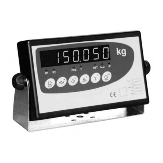
Introduction Display and Luminous Information The indicator consists of a main display and seven luminous indicators, as shown in figure 1.3.1. Figure 1.3.1 Display and luminous Information 1.3.1 Functions Indicator Meaning Tare Scale is in standstill mode Zero Pieces mode Σ... -
Page 12: Label With Characteristics And Metrological Identification
Introduction Label with characteristics and metrological identification It is on the rear side of the indicator, as shown in figure 1.4.1. It is a safety label which contains the characteristics of the device, and metrological values and marks. Figure 1.4.1 Label with characteristics and metrological identification layout... -
Page 13: Error Messages
Introduction Error Messages Main display Condition Solution Scale is not empty Remove the weight EEPROM failure Contact your technical service Data memory failure Contact your technical service No signal from the load cell Check connector and load cell cable ADC error Check connector and load cell cable ADC failure Contact your technical service... -
Page 14: Maintenance
Introduction Maintenance 1.6.1 Replacing Fuses If displays do not appear when it is connected to power, the problem may be a defective ac power fuse. Replace the defective fuse as specified below. Disconnect the indicator by pressing the rear switch and unplug the equipment from the electric outlet. -
Page 15: Operation
Operation Operation Turning the indicator on To turn the indicator on, you must connect the equipment to the power supply and activate the rear switch. The switch on sequence will first display a display test countdown sequence, then the software version, the equipment serial number, and finally the number of performed calibrations. -
Page 16: Zero
Operation Zero The indicator has a zeroing manual mechanism. When you press the Zero key the indicator stores the current weight value as the zero of the system. Operation: Tare 2.5.1 Activate tare Press the Tare key. The current value will be stored as tare. The NET led lights Operation: 2.5.2 Clearing a Tare Value... -
Page 17: Piece Counting
Operation Piece Counting Place a certain number of pieces on the scale, press the Piece Counting key and enter the number of pieces on the scale. The PCS led lights. From now on the indicator displays the number of pieces. Operation: →No.pieces→... -
Page 18: Setpoint
Operation Figure 2.8.1 shows a ticket example. Ticket No. 100.0 kg 200.0 kg 300.0 kg 400.0 kg 500.0 kg Total: 1500.0 kg Figure 2.8.1 Ticket example Setpoint (Accessible only after having installed the digital output accessory) Pressing the Exit and Tare keys at the same time you access the menu where you can introduce the weight with which the selected output operates. -
Page 19: Communications
Operation Exit: EXIT When parameter d_loc is on then the message loc (locked) will be shown and blink three times. 2.10 Communications This equipment has one serial communication port: Port Rx/Tx: transmission and reception serial port The communication channel can be configured from the Configuration Menu (see 3.4). A second transmission channel is available as an optional extra. - Page 20 Operation Weight (7 digits) REMOTE Mode: It allows changing the i digital output, provided that this is programmed TYPE(i) = REM (see 3.7.3) Act: Consult: Answer: Data transfer in ASCII format: Digital output number (1 - 4) Status of the digital output (n): 0 = OFF; 1 = ON Read digital inputs: It allows reading the status of the digital inputs Consult:...
- Page 21 Operation 2.10.1.2 Data Format F1 Format: <STX> ppppppp F2 Format: ‘’ nnnnnnn F3 Format: <STX> ‘1’ ‘ ‘ ‘0’ ‘ ’ nnnnnnn <ETX> F4 Format: aaaaaaa F5 Format: <STX> ‘ ’ nnnnnnn <ETX> F6 Format: For UTILCELL remote display. The content of the display is transmited in hexadecimal.
- Page 22 Operation Format F8: <STX> ‘ ‘ ppppppp ‘ ‘ Unit Unit ‘ ‘ Mode Mode ‘ ‘ UNITS: kg = ‘KG’ MODE: Gross= ‘BR’ lb = ‘lb’ Net= ‘NT’ Format F9: ppppppp Format F10: <STX> <STA> ppppppp <STA>: status, 1 character: "+" positive weight "-"...
-
Page 23: Network Communications (Rs-485)
Operation nnnnnnn Net weight value, 7 characters aaaaaaa Analog/Digital converter filtered output, 7 characters Polarity: ‘ ‘ Weight > 0 ‘-‘ Weight < 0 Units: ‘ ‘ oz, without unit Bruto/Neto: Gross Status: ‘ ‘ Valid Motion Overload Invalid Termination: CR + LF (ASCII 6) (ASCII 21) -
Page 24: Automatic Operations Ports Rx/Tx And Tx
Operation Slave response: > TERMIN Termination (see 3.4.7) Response Address (2 bytes decimal, see 3.4.10) Start slave response There are three types of responses: Data Received and responded query command Received and understood command Received but not understood command 2.11 Automatic operations ports Rx/Tx and Tx When the option MODO (type) of the recepción/transmisión port (Rx/Tx) or the transmission port (Tx) is AUTO, autoti or autoto (see sections 3.4 and 3.5) then the... -
Page 25: Remote Display
Operation 2.12 Remote display To operate the indicator as a Remote display, it should be activated in the equipment configuration (see 3.2.1). After activating the equipment, it will only operate as a remote display of another indicator, which should be connected according to the specifications in 5.8. Configure the following parameters to establish a communication between the two equipments: Parameters... -
Page 27: Configuration And Calibration
Configuration and Calibration Configuration and Calibration Introduction Configuration and calibration modes have different parameters: -Free access, they can always be read and modified. -Protected, they can always be read but only modified under certain conditions (tagged with a in the diagrams). Calibration and configuration modes can be activated by pressing the Setup key and zero key simultaneously. - Page 28 Configuration and Calibration Within the calibration and configuration menu, the display shows your position. Use the key arrows to move through the menus. Use the left and right arroy keys ) to move within the same level, and press the Enter and Exit keys to change the level. If you want to modify a selected parameter, press the Enter key and introduce the new value with the up and down arrow keys ( ) or choose and option (...
-
Page 29: Scale Definition
Configuration and Calibration Scale Definition Within the Scale Definition configuration level, parameters showed in Figure 3.2.1 can be found. repeat indica none Figure 3.2.1 Scale Definition... -
Page 30: Operation (Funct)
Configuration and Calibration 3.2.1 Operation (funct) It selects the operation mode of the equipment. These are the options: Indica: Operation in the indicator mode Repeat: Operation in the remote display mode (see 2.10) 3.2.2 Range (birange) Activates the Multiple Ranges function. In ON position, the menu allows the access to MAX1, DIV1, DP1, MAX2, DIV2 and DP2 parameters, and MAX, DIV and DP2 disappear from the menu (see 3.2.1). -
Page 31: Zero Track (0-Trac)
Configuration and Calibration 3.2.12 ZERO TRACK (0-trac) The level at which the system is automatically zeroed as long as the weight is within the selected band. These are the options: OFF: Deactivated function ± 0.5 divisions 0,5dd: ± 1 division 1dd: ±... -
Page 32: Options
Configuration and Calibration Options Within the Options configuration level, parameters showed in Figure 3.3.1 can be found. t a r e l o c 1d 2d fre eng 16 32 64 Prog Prog 0 0 0 0 0 0 Figure 3.3.1 Options... -
Page 33: Filter (Filter)
Configuration and Calibration 3.3.1 FILTER (filter) Filter level. You can choose among different levels or deactivate this function. The higher the selected value is, the higher the filter level is These are the options: OFF, 2, 4, 8, 16, 32, 64 3.3.2 MOT BAND (band) The level at which motion is detected. -
Page 34: Print Min (Prt)
Configuration and Calibration 3.3.6 PRINT MIN (prt) Minimum weight value in divisions at which a print ticket request may be accepted. If the ticket cannot be printed “ ” will be displayed. 3.3.7 TICKET(prt_t1) Selects the type of ticket to be printed with the Print key. These are the options: OFF: No ticket printing... -
Page 35: Communication Port
Configuration and Calibration Communication Port Within the communication port, parameters showed in Figure 3.4.1 can be found. De st Auto Autot F2 F3 F4 F5 F6 F7 F12 F13 500 1000 2000 4800 9600 19200 Cr Et None Rs-485 Crlf rs-232 Figure 3.4.1 Communication port 3.4.1... -
Page 36: Band(Band)
Configuration and Calibration AUTO TICKET (autoti): A ticket is automatically printed on acomplishing the º condition for automatic operations on ports (see 2.11). AUTO TOTAL (autoto): Totalizes automatically on acomplishing the condition for automatic operations on ports (see 2.11). 3.4.2 BAND(band) Only accessible if the options AUTO, AUTO TICKET and AUTO TOTAL are activated in the MODE parameter. -
Page 37: Control (Cntl)
Configuration and Calibration 3.4.8 CONTROL (cntl) Control of the hardware flow (RTS signal of the RS-232-C protocol) These are the options: OFF: Deactivated function Activated function 3.4.9 PORT (port) Port selection enabled. If “RS-232” is selected, the ADD parameter is forced to be “0”. 3.4.10 ADD (add) Address of the equipment in a RS-485 network. -
Page 38: Transmission Port
Configuration and Calibration Transmission Port (Accessible only after having installed the RS-232 second port accessory) Within the configuration transmission port, parameters showed in Figure 3.5.1 can be found. OFF st ti auto autot f1 f2 f3 f4 f5 f6 f7 f8 f9 f10 f11 f12 f13 4800 9600... -
Page 39: Mode(Type)
Configuration and Calibration 3.5.1. MODE(type) Transmission mode. These are the options: OFF (off): Data transmission deactivated STREAM (st): Continuous data transmission TICKET (ti): Transmission on a print internal request (Print key) AUTO (auto): It is automatically transmitted on acomplishing the condition for automatic operations on ports (see 2.11). -
Page 40: Control (Cntl)
Configuration and Calibration CR+LF <CR>,<LF> <CR> <ETX> NONE NOTHING 3.5.8. CONTROL (cntl) Control of the hardware flow (RTS signal of the RS-232-C protocol) OFF: These are the options: Deactivated function Activated function Analog Output (Accessible only after having installed the Analog Output accessory) Within the analog output configuration level, parameters showed in Figure 3.6.1 can be found. -
Page 41: Type(Type)
Configuration and Calibration 3.6.1 TYPE(type) Weight value of analog output signal. These are the options: GROSS: Gross weight value is taken as reference NET: Net weight value is taken as reference 3.6.2 OFFSET (offset) Analog output zero offset. These are the options: 0% y 20%. -
Page 42: Digital Outputs
Configuration and Calibration Digital outputs (Accessible only after having installed the Digital Outputs accessory) Within the digital outputs configuration level, parameters showed in Figure 3.7.1 can be found. gross p_rel n_rel p_prel n_prel 0ero 0net inrang tare print pc_ctr l in_b out_b Figure 3.7.1 Digital outputs 3.7.1 D_OUT Nº... -
Page 43: Type(I) (Type)
Configuration and Calibration 3.7.3 TYPE(i) (type) Type of output action. These are the options: OFF (off): Deactivated GROSS (gross): Gross weight value as reference NET (net): Net weight value as reference +REL (p_rel): Setpoint trips on the absolute setpoint value, VL(i), plus the relative value, REL(i) -REL (n_rel): Setpoint trips on the absolute setpoint value, VL(i),... -
Page 44: Band(I) (Bd)
Configuration and Calibration 3.7.6 BAND(i) (bd) A numerical value which determines the value of the IN_B and OUT_B selections of the TRIP parameter. 3.7.7 HYSTERESIS(i) (hy) Determines the hysteresis value which prevents chattering of the digital output 3.7.8 LOCKED (D_LOC) It blocks the modification of VL(i) value through the keyboard (see 2.9) 3.7.9 OUTPUT(i) (output) - Page 45 Configuration and Calibration Figure 3.7.9.3 Setpoint TRIP Actions 3-19...
-
Page 46: Digital Inputs
Configuration and Calibration Digital Inputs (For application with Digital Inputs accessory) Within the digital inputs configuration level, parameters showed in Figure 3.8.1 can be found. TARE CTARE 0ERO PRINT CTOT Figure 3.8.1 Digital Inputs 3.8.1 D_IN NUM (d_in no) Number of digital input. These are the options: 1, 2, 3, 4 3.8.2... -
Page 47: Function(I) (Func)
Configuration and Calibration 3.8.3 FUNCTION(i) (func) Input action mode. These are the options: LOW: From HIGH to LOW HIGH: From LOW to HIGH Figure 3.8.3.1 Examples of Application 3-21... -
Page 48: Calibration With Masses
Configuration and Calibration Calibration with Masses Within the calibration with masses level, parameters showed in Figure 3.9.1 can be found. reset Figure 3.9.1 Calibration with Masses 3.9.1 ZERO (0ero) - Automatic zero adjustment: To automatically adjust the zero value make sure there is not any weight on it and press the enter key. -
Page 49: Span (Span)
Configuration and Calibration 3.9.2 SPAN (span) - Automatic span adjustment: To automatically adjust the span, place a certified test weight on the scale and press Enter. The maximum scale value is displayed, if the weight placed on the scale is different, key in the real value. Press the Enter key and *CALIB* is displayed while the unit calculates the span coefficient. - Page 50 Configuration and Calibration Figure 3.9.4.1 Linearity adjustment performance before and afterwards, respectively. This is the procedure: 1-Select Reset in the LIN parameter in order to assess the system linearity without any pre-existing correction. The LIN parameter is deactivated and any previous correction is deleted.
-
Page 51: Numerical Calibration
Configuration and Calibration 3.10 Numerical Calibration If there is no reference weight value, it is possible to make a theoretical calibration using capacity and sensibility values (mV/V) of the load cells used. For a calibration of maximum precision you always have to use the calibration with masses. -
Page 52: Animal-Weigher/Check-Weigher Application
Configuration and Calibration ). If a negative value has to be introduced it can only be done with the first left digit. The negative sign appears after the number 9. When we want to manually introduce the zero value in an indicator with a software version previous to 1.3XX then the last digit has to be truncated. -
Page 53: Init (Init)
Configuration and Calibration 3.11.1 Init (init) Through this option we can activate or deactivate the Animal-weigher/Check-weigher option. It can be activated in print mode or in total mode and be deactivated with off. If it is activated in PRINT mode, the process is started on pressing the key equivalent RS-232 or digital input command) and the indicator prints a ticket on ending. -
Page 54: Tools
Configuration and Calibration 3.12 Tools Within the tools level, parameters showed in Figure 3.12.1 can be found. print int_1 int_6 01 00 12 00 Figure 3.12.1 Tools 3.12.1 Weightx10 (h_res) Displays the weight with a resolution multiplied by ten. 3.12.2 MV-Metro (signal) Displays the ADC output in mV. -
Page 55: Brightness Of Leds (Led Int)
Configuration and Calibration Brightness of LEDs (led int) 3.12.5 The brightness of LEDs may be changed with this tool. The range goes from 1 (minimum value) to 6 (maximum value). The selected brightness is displayed as it is modified. 3.12.6 Date(date) (Accessible only after having installed the Clock accessory) Current date. -
Page 57: Installation
Installation Installation Measures Figure 4.1.1 Measures stainless steel version Figure 4.1.2 Measures ABS version... -
Page 58: Fixed Bracket
Installation Fixed Bracket Bascule bracket for wall, ceiling, structure, etc. mounting. Figure 4.2.1 Fixed Bracket Mounting... -
Page 59: Unit Label
Installation Unit Label Next to the main display, the default units (kg) are silkscreen printed. Adhesives with different units are included. Units: g, t, lb, oz, ton, N, kN and an empty label. Figure 4.3.1 Unit Label... -
Page 60: Ip65 Assembly
Installation IP65 Assembly (Only available in the stainless steel version) To make the appropiate connections in the IP65 indicator (see 5.3), remove the rear cover and pass each connection cord through the designated cable-gland screwing each of them to guarantee that they are properly locked. If any of the connections is not established, do not drill the cable-gland inside part. -
Page 61: Connector Description
Connector description Connector Description Load cell RS-232 Load cell RS-232 Figure 5.1 Connectors Load cell Connector Use a SUBD-9 aerial male connector to connect the load cell to the indicator. Weld wires in accordance with the following tables. For the 6 wire connection it is advisable to bridge 1-6 and 5-9 pins in order to double the excitation signal contact surface. -
Page 62: Load Cell Connector Sealing
Connector description 5.1.1 Load cell connector sealing The sealing of the load cell connector is made by means of a autodestruible sticky label as showed in figure 5.1.1.1. Seal Figure 5.1.1.1 Load cell connector sealing Communication Connectors 5.2.1 RS-232 (Rx/Tx) Connector The indicator connector is a male SUB-D 9. -
Page 63: Ip65 Connections
Connector description IP65 Connections Use the cable-gland that you will find in the equipment rear side for the IP65 indicator connections. Make the connections as shown in figure 5.3.1. Figure 5.3.1 IP 65 Connection WARNING-SHOCK HAZARD Due to the risk of electrical shock, this instrument must be operated only by qualified personnel and be unplugged from the power supply. -
Page 64: Multioption Connection
Connector description RS-232 Connection Load cell Connection UTILCELL SIGNAL SIGNAL Load cell Code SIG + SIG- White Shield Sense + Blue Sense - Yellow EXC - Black EXC + Green Table 5.3.2 6 Wire PIN Allocation If a 4 wire power cord is used, bridge 4-7 pins (EXC+ and SENSE+) and 5-6 (EXC- and SENSE-) in the aerial connector. -
Page 65: Rs-232 (Tx) Connector
Connector description 5.4.1 RS-232 (Tx) Connector The indicator connector is a male SUB-D 9. SIGNAL SUB-D 9 aerial female connector Pin allocation welding's side view Tabla 5.4.1.1 RS-232 (Tx). Connector Allocation Digital/Analog input/Output and RS-485 connector The indicator connector is a male SUB-D 25. DIGITAL INPUT SIGNAL DIGITAL OUTPUT... -
Page 66: Ip65 Multioption Connection
Connector description IP65 Multioption connection For the connections of the IP65 Multioption indicator as well as the connections of the IP65 (see 5.3) perform the connections shown in figure 5.6.1. DATA+ RS-485 DATA- A - B RTERM OFF B - C RTERM ON Analog Output Digital Input Power Supply... -
Page 67: Jumpers' Position Rs-232
Connector description Jumpers’ position RS-232 If the equipment has multioption board (Multi1 or Multi2) the positions of jumpers J4 and J8 have to be changed as indicated in figure 5.7.1 Normal Position Position for equipements with Multi1 or Multi2 board Figure 5.7.1 Jumpers’... - Page 68 NOTES __________________________________________________ __________________________________________________ __________________________________________________ __________________________________________________ __________________________________________________ __________________________________________________ __________________________________________________ __________________________________________________ __________________________________________________ __________________________________________________ __________________________________________________ __________________________________________________ __________________________________________________ __________________________________________________ __________________________________________________ __________________________________________________ __________________________________________________ __________________________________________________ __________________________________________________ __________________________________________________ __________________________________________________ __________________________________________________ __________________________________________________ __________________________________________________ __________________________________________________ __________________________________________________ __________________________________________________ __________________________________________________ __________________________________________________ __________________________________________________ __________________________________________________ __________________________________________________ __________________________________________________ __________________________________________________...
- Page 69 NOTES...
- Page 70 NOTES __________________________________________________ __________________________________________________ __________________________________________________ __________________________________________________ __________________________________________________ __________________________________________________ __________________________________________________ __________________________________________________ __________________________________________________ __________________________________________________ __________________________________________________ __________________________________________________ __________________________________________________ __________________________________________________ __________________________________________________ __________________________________________________ __________________________________________________ __________________________________________________ __________________________________________________ __________________________________________________ __________________________________________________ __________________________________________________ __________________________________________________ __________________________________________________ __________________________________________________ __________________________________________________ __________________________________________________ __________________________________________________ __________________________________________________ __________________________________________________ __________________________________________________ __________________________________________________ __________________________________________________ __________________________________________________...
- Page 71 NOTES...
Need help?
Do you have a question about the Smart Series and is the answer not in the manual?
Questions and answers