Table of Contents
Advertisement
Advertisement
Table of Contents

Summary of Contents for JCM GLOBAL VEGA 100
- Page 1 July, 2013 JCM TRAINING OVERVIEW VEGA™ Banknote Acceptor Phone # (800) 683-7248 (702) 651-0000 Technical Support # (702) 651-3444 Fax # (702) 651-0214 E-mail techsupport@jcmglobal.com Web Address http://www.jcmglobal.com © 2013, JCM American, Corporation Part No. 960-000165R_Rev. 1...
-
Page 2: Table Of Contents
VEGA™ Banknote Acceptor JCM Training Overview July, 2013 VEGA™ Banknote Acceptor Table of Contents Page Overview.................. 3 VEGA Unit....................3 VEGA Features ............... 4 User Precautions ..............5 Component Locations.............. 6 Component Names..............6 Installation................7 VEGA SH Unit...................7 VEGA SU/SD Unit..................7 VEGA SU/SD Unit (Continued 1) ................8 VEGA SU/SD Unit (Continued 2) ................9 DIP Switch Settings ............... -
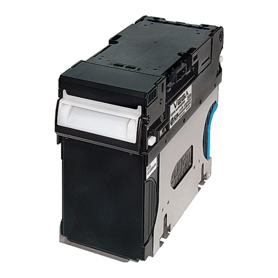
Page 3: Overview
OVERVIEW This training course addresses the following JCM VEGA™ device versions: Table 1 Various VEGA Versions Device Capacity/Contents VEGA 100 12V DC Power (NO Magnetic Sensor) VEGA 101 12V DC Power / Magnetic Sensor (W) VEGA 102 24V DC Power / NO Magnetic Sensor... -
Page 4: Vega Features
VEGA™ Banknote Acceptor JCM Training Overview July, 2013 VEGA FEATURES The VEGA Unit contains the following features: • Works as a stand-alone Bill Validator, or with optional equipment • Combined with the RC-30, it provides a Banknote Recycling capability • Accepts foreign and U.S. Banknotes 110-165 mm Long by 60-82 mm Wide •... -
Page 5: User Precautions
July, 2013 JCM Training Overview VEGA™ Banknote Acceptor USER PRECAUTIONS The following User precautions should be observed when installing, operating and servicing a VEGA Unit: • When closing the Upper portion of the Transport path or the Course Path Reversing Guide Cover, ensure that it clicks firmly into place •... -
Page 6: Component Locations
VEGA™ Banknote Acceptor JCM Training Overview July, 2013 COMPONENT LOCATIONS Component Names Figure 2 illustrates the VEGA Component Names and Locations. Left Side Right Side Bottom Back Side Front Side a) Upper Section i) Course Path Reversing Guide b) Bezel j) Course Path Reversing Guide Cover c) Upper Section Open/Close Buttons Release Buttons... -
Page 7: Installation
July, 2013 JCM Training Overview VEGA™ Banknote Acceptor INSTALLATION VEGA SH U Perform the following steps to install a VEGA SH Unit into a Host Machine: 1. Mount the VEGA SH Unit in place without the Cash Box installed. 2. Bolt the bottom of the VEGA Frame into place using four (4) M4 Hex- nuts (See Figure 3 &... -
Page 8: Vega Su/Sd Unit (Continued 1)
VEGA™ Banknote Acceptor JCM Training Overview July, 2013 VEGA SU/SD Unit (Continued 1) 6. Connect the attached Bezel Plate (See Figure 4 a) on the VEGA SD/ SU Bracket (See Figure 4 b) using two (2) M4 screws (See Figure 4 &... -
Page 9: Vega Su/Sd Unit (Continued 2)
July, 2013 JCM Training Overview VEGA™ Banknote Acceptor VEGA SU/SD Unit (Continued 2) 10.Turn the VEGA Unit's power ON. This concludes the VEGA SU/SD Installation Procedure. Figure 6 Cash Box and Guide Cover Lecture Notes Part No. 960-000165R_Rev. 1 © 2013, JCM American, Corporation... -
Page 10: Dip Switch Settings
VEGA™ Banknote Acceptor JCM Training Overview July, 2013 DIP SWITCH SETTINGS The VEGA Banknote Validator contains three (3) DIP Switch Blocks (i.e., DS1, DS2, and DS3). They are located in the center of the top of the Unit approximately two (2) inches from the front of the Unit (Review Figure 2 h). •... -
Page 11: Functional Testing
July, 2013 JCM Training Overview VEGA™ Banknote Acceptor FUNCTIONAL TESTING DIP S WITCH Perform the following steps to test the functionality of each DIP Switch Block: 1. Ensure that the VEGA's Power is 2. Set all DIP Switches on DS 1 and DS 2 to the position. -
Page 12: Feed Motor Reverse Rotation Test
VEGA™ Banknote Acceptor JCM Training Overview July, 2013 OTOR EVERSE OTATION Perform the following steps to test the normal reverse rotation functionality of the Feed Motor: 1. Ensure the VEGA's Power is 2. Set DS1, Switches #1, & #2 3. Apply Power to the VEGA. 4. -
Page 13: Aging Test
July, 2013 JCM Training Overview VEGA™ Banknote Acceptor GING Perform the following steps to repeatedly test the VEGA's basic feeding, trans- porting, and stacking functions: 1. Ensure the VEGA's power is 2. Set DS1, Switches #1, #2 & #4 3. Apply power to the VEGA. 4. -
Page 14: Sensor Test (Continued)
VEGA™ Banknote Acceptor JCM Training Overview July, 2013 Sensor Test (Continued) Table 8 lists the DS2 settings for the Sensor Test configuration. Select the intended Sensor from the Table, and set the DS2 Switches according to the Table Switch positions. Table 8 DIP Switch Block DS2 Sensor Configuration Settings DIP Switch Block DS2 Yellow LED State... -
Page 15: Software Download Procedure
July, 2013 JCM Training Overview VEGA™ Banknote Acceptor SOFTWARE DOWNLOAD PROCEDURE Perform the following steps to download the VEGA Operating Software Program (Refer to Figure 7 for the Tool Requirements and Harness Connector locations). However, before downloading the VEGA Software Program, copy the Downloader Program (UBA Down- loader Version 2.10: specified), and the VEGA Operating Software Pro-... -
Page 16: Software Download Procedure (Continued 1)
VEGA™ Banknote Acceptor JCM Training Overview July, 2013 OFTWARE OWNLOAD ROCEDURE ONTINUED 6. Mouse-click the " " Browse Screen Button (See Figure 8 a) and select the desired VEGA Software for down- load into the VEGA Flash Memory; then, 7. Mouse-click on the " "... -
Page 17: Software Download Procedure (Continued 2)
July, 2013 JCM Training Overview VEGA™ Banknote Acceptor OFTWARE OWNLOAD ROCEDURE ONTINUED 9. Once the download is com- plete, the Front Panel LED Display turns a steady Blue Color, and then the VEGA returns to a Start-up Process condition (e.g., the Front Panel LED Display blinks at a Green... -
Page 18: Non-Pc Calibration Procedures
VEGA™ Banknote Acceptor JCM Training Overview July, 2013 NON-PC CALIBRATION PROCEDURES When removing or replacing the Sensor, Sub-Sensor, or CPU Board, perform the following steps to calibrate the Entrance, Validation, and Edge Sensors of the VEGA Unit. NOTE: If any of the Sensors are dirty the calibration will not be accurate. -
Page 19: Non-Pc Calibration Procedures (Continued)
July, 2013 JCM Training Overview VEGA™ Banknote Acceptor -PC C ALIBRATION ROCEDURES ONTINUED 8. Set the White Reference Paper in place. 9. Set DS 2, Switch #2 to ON to begin the Validation Sensor Adjustment. 10.The White Reference Paper Adjustment is complete when the Front Panel LED blinks at a Blue Color Rate. -
Page 20: Off-Line Banknote Acceptance Test
VEGA™ Banknote Acceptor JCM Training Overview July, 2013 ANKNOTE CCEPTANCE Perform the following steps to perform the VEGA's Off-Line Banknote Acceptance Test. 1. Ensure the VEGA's power is OFF. 2. Set DS1, Switches #1, #3 & #5 ON. 3. Apply power to the VEGA. 4. -
Page 21: Error And Reject Code Tables (Continued)
July, 2013 JCM Training Overview VEGA™ Banknote Acceptor Error and Reject Code Tables (Continued) Table 11 lists the various VEGA Reject Code LED combinations. Table 11 LED Reject Codes On-Line Off-Line Error Possible Cause Color Flashes Color Flashes (mSec) (mSec) Sensor does NOT detect Banknote even though the number of Banknotes Yellow 3 (120) White 3 (300) -
Page 22: Vega Parts List
VEGA™ Banknote Acceptor JCM Training Overview July, 2013 VEGA PARTS LIST Part Number Description • 190876 Reference Paper (White: KS-325) • 190875 Reference Paper (Black: KS-326) • 302-100011R USB Male 'A' to USB 'Mini-B' Cable • 501-100218R UAC Module • 400-100669R UAC Adapter Harness (ID-003) •... - Page 23 July, 2013 JCM Training Overview VEGA™ Banknote Acceptor PERSONAL NOTES AND COMMENT AREA Write any pertinent notes or comments regarding your particular installation here. Lecture Notes Part No. 960-000165R_Rev. 1 © 2013, JCM American, Corporation...
- Page 24 July, 2013 JCM Training Overview VEGA™ Banknote Acceptor JCM is a registered trademark of JCM American Corporation. All other product names mentioned herein may be registered trademarks or trademarks of their respective companies. ™ ® © Furthermore, are not always mentioned in each case throughout this publication. 925 Pilot Road, Las Vegas, Nevada 89119 Office &...
Need help?
Do you have a question about the VEGA 100 and is the answer not in the manual?
Questions and answers
Hello, I have a Japan Cash Machine (VEGA-100) but I don’t have a cash box. My question is: Does the VEGA-100 work without a cash box? If it does not work without a cash box, how can I operate it without one? If it is suitable to run without a cash box, I will use it like that, but if not, I will buy a cash box.