Advertisement
OWNER'S MANUAL
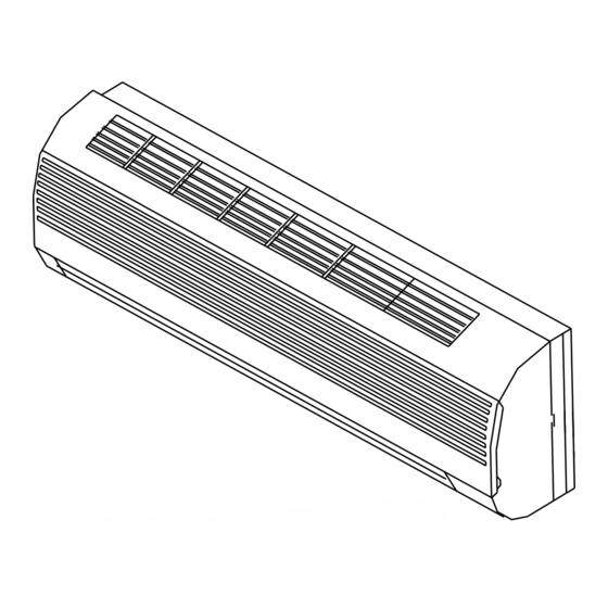
HI-WALL AIR CONDITIONER
Thank you for selecting CIAC Air Conditioning. Before use, please read this manual carefully
and store it for future reference.
This manual applies to models:
CG21A/ CH21A
CG41A/ CH41A
CG42A/ CH42A
CG21V/CH21V
Carrier InterAmerica Corporation
Miami, Florida USA
HI-WALL SPLIT 60 /50 HZ
CG21A/ CH21A R-22
CG21V/ CH21V R-22
CG41A/ CH41A R-410A
CG42A/ CH42A R-410A
CG/CH21,41,42AM3-IOM
Advertisement
Table of Contents

Related Manuals for CIAC CG21A


Summary of Contents for CIAC CG21A
- Page 1 HI-WALL AIR CONDITIONER This manual applies to models: CG21A/ CH21A CG41A/ CH41A CG42A/ CH42A CG21V/CH21V Thank you for selecting CIAC Air Conditioning. Before use, please read this manual carefully and store it for future reference. Carrier InterAmerica Corporation Miami, Florida USA CG/CH21,41,42AM3-IOM...
-
Page 2: Table Of Contents
C O N T E N T S S A F E T Y PR E C A U T I ON S ....................1 ......................3 NA ME S OF T HE PA RT S INDOOR UNIT DISPL AY ......................4 E ME R GE NCY FUNCT ION & A UTO-R E STA RT FUNCT ION ..........5 R E MOT E CONT R OL .......................6... - Page 3 SAFETY RULES AND RECOMMENDATIONS FOR THE INSTALLER Do not install the unit at a distance Read this guide before installing and using the less than 50 cm from in ammable substances appliance. (alcohol, etc.) Or from pressurised containers During the installation of the indoor and outd- (e.g.
-
Page 4: Safety Precautions
SAFETY RULES AND RECOMMENDATIONS FOR THE USER This unit has been designed for air conditi- Disconnect main power if unit is not to be used oning domestic use and must not be for a prolonged period. applied for any other purpose. For best results, the air ow direction aps The packaging materials are recyclable and should be directed downward in the heating... -
Page 5: Names Of The Parts
NAMES OF THE PARTS INDOOR UNIT Description Front panel Air lter Optional lter (if installed) LED Display Remote control signal receiver Terminal block cover Ionizer generator (if installed) Air de ectors Emergency button Indoor unit rating label Air ow direction aps Remote control OUTDOOR UNIT Description... -
Page 6: Indoor Unit Display
INDOOR UNIT DISPLAY Function Shows that the unit is powered POWER SLEEP mode SLEEP Indicates the set temperature in Temperature display (if present) TIMER TIMER mode Unit working The shape and position of switches and indicators may vary according to the model, but their function is the same. -
Page 7: Emergency Function & Auto-Restart Function
EMERGENCY FUNCTION & AUTO-RESTART FUNCTION AUTO-RESTART FUNCTION The unit is preset to auto - restart function by the manufacturer.With this function the air conditioner ON / OFF can keep the selected settings after a blackout or a voltage drop To deactivate the AUTO-RESTART function: Emergency 1. - Page 8 REMOTE CONTROL Button Function (TEMP UP) Increase the temperature or time by 1 unit (TEMP DN) Decrease the temperature or time by 1 unit ON/OFF To switch the conditioner on and o . C L OC K DIS P L AY HE A LT HY To select the fan speed of auto/low/mid/high ON/OF F...
-
Page 9: Remote Control
REMOTE CONTROL Remote control DISPLAY Meaning of symbols on the liquid crystal display No. Symbols Meaning FEEL mode indicator HEALTHY TIMER COOLING indicator DEHUMIDIFYING indicator FAN ONLY OPERATION indicator HEATING indicator SIGNAL RECEPTION indicator FEEL SPEED AUTOQUIET COOL POWERFUL TIMER OFF indicator SWING TIMER DELAY... - Page 10 REMOTE CONTROL Preliminary Instructions How to insert the batteries Remove the cover from the battery compartment , by sliding it in the direction of the arrow Insert the new batteries, ensuring that the (+) and (-) directions are correct Re t the cover by sliding it into place. Use 2 AAA (1.5V) batteries .
- Page 11 MODES OF OPERATION The conditioner is designed to create the comfortable climatic conditions for the people in the room. Filter It can cool and dehumidify (and heat in models with heat pump) the air in a completely automatic way. Heat The air drawn in by the fan enters at the front grill of the Exchanger panel and passes through the lter.
- Page 12 MODES OF OPERATION COOLING MODE COOL FEEL The cooling function allows the air condit- COOL SPEED AUTOQUIET COOL POWERFUL ioner to cool the room and at the same time SWING reduces the humidity in the air. DELAY HEAT To activate the cooling function ( COOL ) , press the HEALTHY TIMER MODE button until the symbol...
- Page 13 MODES OF OPERATION TIMER MODE----TIMER ON TIMER To set the automatic switching-on of FEEL SPEED AUTOQUIET COOL the air conditioner POWERFUL TIMER SWING DELAY HEAT To program the time start,the appliance should be off. HEALTHY TIMER Press TIMER , Set the temperature with pressing the ,Press TIMER Again , set the time with pressing the key , Press the key more times till...
- Page 14 MODES OF OPERATION FAN MODE The conditioner works in only FEEL SPEED AUTOQUIET COOL ventilation. POWERFUL SWING DELAY HEAT To set the FAN mode , Press MODE untill HEALTHY TIMER ( FAN ) appears in the display. Whith pressing button the speed changes ON/OFF in the following sequence: LOW/ MEDIUM/HIGH /AUTO in FAN mode.
- Page 15 MODES OF OPERATION FEEL MODE FEEL Automatic mode. FEEL FEEL SPEED AUTOQUIET COOL POWERFUL SWING DELAY HEAT To activate the FEEL (automatic) mode of operation, HEALTHY TIMER press the MODE button on the remote control until the symbol ( FELL ) appears in the display.
- Page 16 PROTECTION The protective device maybe trip and stop the appliance in the cases listed below. For T1 Climate condition models: MODEL Outdoor air temperature is over 24 Outdoor air temperature is below -7 Heating Room temperature is over 27 Outdoor air temperature is over 43 Cooling Room temperature is below 21 Room temperature is below 18 C...
-
Page 17: Installation Manual
INSTALLATION MANUAL---Selecting the Installation Place INDOOR UNIT Install the indoor unit level on a strong wall that is not Mounting plate subject to vibrations. The inlet and outlet ports should not be obstructed:the air should be able to ow to the entire area. Do not install the unit near a heat source , steam,or any ammable source. -
Page 18: Safety
INSTALLA TION MANUAL---Installation of the Indoor unit Before starting installation, determine on the position and location of the indoor and outdoor units, taking into account the minim- um space required around the units Install the indoor unit in the room to be air conditio- ned, avoiding to install in corridors or common areas. - Page 19 INSTALLA TION MANUAL---Installation of the Indoor unit Refrigerant piping connection The piping can be run in the 3 directions as indicated by numbers in the picture . When the piping is run in direction 1or3, cut a notch along the groove on the side of the indoor unit.
- Page 20 INSTALLATION MANUAL---Installation of the Indoor unit INSTALLATION OF THE INDOOR UNIT After having connected the pipe according to the instruc- Covered by vinyl tape tions, install the connection cables. Now install the drain refrigerant insulation pipe. After connection, wrap the pipe, cables and drain pipe pipe sleeve connection...
- Page 21 INSTALLATION MANUAL---Installation of the outdoor unit ELECTRICAL CONNECTIONS wiring diagram on the back of the cover 1. Remove the electrical box cover. 2. Connect the wires the terminal board using the same numbering as in the indoor unit. 3. For the electrical connections, see the wiring diagram on the back of the cover 4.
- Page 22 INSTALLATION MANUAL---Installation of the outdoor unit EVACUATION AND DEHYDRATION 3-way valve diagr am connect to indoor unit (1) Unscrew and remove the caps from the 2 - way and open position 3-way valves. spindle (2) Unscrew and remove the cap from the service port. (3) Connect the vacuum pump hose to the service port.
- Page 23 INSTALLATION MANUAL---Information for the installer FIXED-SPEED TYPE MODEL capacity (Btu/h) Liquid pipe diameter ( 6) ( 6) ( 6) ( 9.52) Gas pipe diameter ( 9.52) ( 15.88) Lenght of pipe with standard charge Maximum distance between indoor and outdoor unit 20g/m 20g/m 30g/m...
- Page 24 INSTALLATION MANUAL---Information for the installer WIRING DIAGRAM FOR 22K-24K-28K-30K COOLING ONLY MODELS FOR 5K-7K-9K-12K-18K COOLING ONLY MODELS (FOR 9K-12K-18K-24K COOLING ONLY MODELS TO NORTH AMERICAN MARKET) INDOOR UNIT INDOOR UNIT POWER SUPPLY OUTDOOR UNIT OUTDOOR UNIT POWER SUPPLY FOR 7K-9K-12K-18K HEAT PUMP MODELS FOR 22K-24K-28K-30K HEAT PUMP MODELS (FOR 9K-12K-18K-24K HEAT PUMP MODELS TO NORTH AMERICAN MARKET)
- Page 25 INSTALLATION MANUAL---Information for the installer CABLE WIRES SPECIFICATION MODEL capacity (Btu/h) sectional area 1.0mm 1.0mm 1.5mm 2.5mm (1.5mm) AWG18 AWG18 AWG16 AWG14 (AWG16) Power supply cable 1.0mm 1.0mm 1.5mm 2.5mm (1.5mm) AWG18 AWG18 AWG16 AWG14 (AWG16) 1.0mm 1.0mm 1.5mm 2.5mm (1.5mm) AWG18 AWG18...
-
Page 26: Maintenance
MAINTENANCE Periodic maintenance is essential for keeping your air conditioner at peak operation. Before carrying out any maintenance , disconnect the power supply by putting the installation on/ o switch to INDOOR UNIT ANTIDUST FILTERS 1. Open the front panel following the direction of the arrow 2. -
Page 27: Troubleshooting
TROUBLESHOOTING MALFUNCTION POSSIBLE CAUSES Power failure/disconnected, breakers tripped. Damaged indoor/outdoor unit fan motor Faulty compressor The unit does not Faulty protective device or fuses. operate Loose connections Stopped due to protection device. Voltage higher or lower than the voltage range Active TIMER-ON function Damaged electronic control board Dirty air lter...
Need help?
Do you have a question about the CG21A and is the answer not in the manual?
Questions and answers
how do i turn off the bright LED display on the minisplit head?
To turn off the bright LED display on the CIAC CG21A minisplit head, press the "DISPLAY" button on the remote control.
This answer is automatically generated
@Mr. Anderson there is no such button on the remote, see photo. the answer in to hit "menu/ok" , use arrows to highlight "sleep" and press "menu/ok" thank you for your comment
How can I move the small flaps
You must not move the small flaps manually, as this could seriously damage the delicate mechanism that activates them. Use the controls to adjust flap movement instead. Always switch off the unit before adjusting deflectors, which are different from the flaps.
This answer is automatically generated
H2 sign showing. Doesn’t want to turn off