Advertisement
Installation
1. To assure proper installation, measure the voltage on
each phase and ensure the correct device is installed.
2. Turn off power to the circuit where surge protector is to
be installed.
3. Mount device to keep conductor length as short as
possible. Cut wires to length and connect to circuit per
wiring diagram below avoiding sharp bends or looping.
4. Splice the included Rectorseal RSH60-VMD 24V
thermostat control wires into the Y1 terminal
thermostat wire.
5. Reinstall covers, restore power and confirm diagnostic
LED is illuminated.
Device Ratings
Normal Voltage
Max. Operating Voltage
Per Leg
(MCOV) Per Leg
120 VAC
150 VAC
Para instrucciones en español visite www.rectorseal.com
Technical Support Call 1-800-648-6802
All surge protection devices require a good ground connection for effective operation
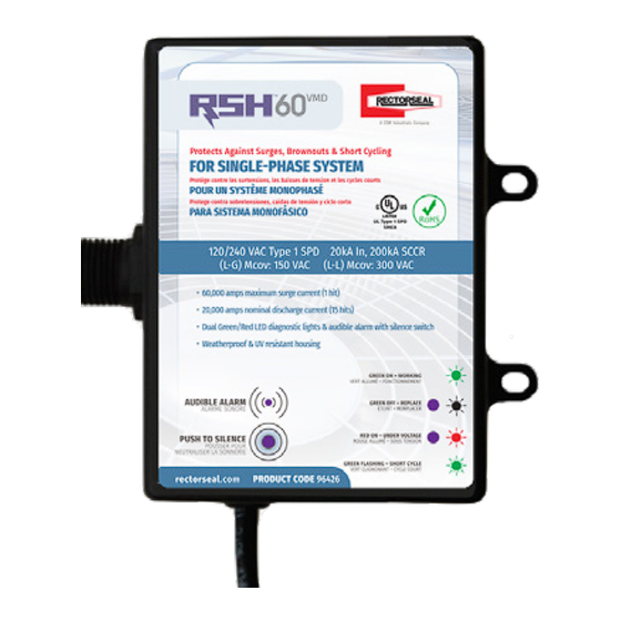
Surge Protective Device (SPD) & Voltage Monitoring
120 VAC DIAGRAM
Single-Phase System: 1 Ph, 2W + G
120 VAC
Max. Discharge
Diagnostic Operations
Current (IMAX)
CONDITION
60kA
Surge Protection
No Surge Protection
Under Voltage
Short Cycle Protection
Opérations de diagnostic
ÉTAT
Protection Contre
Les Surtensions
I N S T A L L A T I O N I N S T R U C T I O N S
Device (VMD) for Single-Phase System
240 VAC DIAGRAM
Split-Phase System: 1 Ph, 2W + G
240 VAC
RSH-60 VMD
RSH-60 VMD
120 VAC
120 VAC
24 VAC
24 VAC
Y1
Y1
Y1
Y1
GREEN LED
RED LED
AUDIBLE ALARM
ON
––
OFF
ALTERNATIVE WIRING METHOD:
OFF
––
ON
This SPD can be also be installed by splicing into the wires of the
––
ON
––
WIP, within the disconnect box or by using a double lug adapter.
FLASH
––
––
LED VERT
LED ROUGE
ALARME AUDITIVE
ALLUMÉ
––
ÉTEINDRE
240 VAC 2-Pole
Disconnect Diagram
Ground
Green
Black
Black
Advertisement
Table of Contents

Summary of Contents for CSW RECTORSEAL RSH-60 VMD
- Page 1 I N S T A L L A T I O N I N S T R U C T I O N S Surge Protective Device (SPD) & Voltage Monitoring Device (VMD) for Single-Phase System Installation 1. To assure proper installation, measure the voltage on each phase and ensure the correct device is installed.
- Page 2 RectorSeal, LLC • 2601 Spenwick Drive, Houston, TX 77055, USA • 800-231-3345 • Fax 800-441-0051 • rectorseal.com A CSW Industrials Company. RectorSeal, the logos and other trademarks are property of RectorSeal, LLC, its affiliates or its licensor’s and are protected by copyright, trademark and other intellectual prop-...
Need help?
Do you have a question about the RECTORSEAL RSH-60 VMD and is the answer not in the manual?
Questions and answers