
Related Manuals for AR PL7004


Summary of Contents for AR PL7004
-
Page 1: Service Manual
Operating and Service Manual PL7004 Model 10024183 Part Number Serial Number 160 School House Road, Souderton, PA 18964 • 215-723-8181 • Fax 866-859-0582 • www.arworld.us... -
Page 3: Declaration Of Conformity
REGULATION (EC) 1907/2006 OF THE EUROPEAN PARLIAMENT AND OF THE COUNCIL of 18 December 2006 concerning the Registration, Evaluation, Authorization and Restriction of Substances of Very High Concern Chemicals (SVHC) Supporting documentation is held by AR RF/Microwave Instrumentation’s Quality department in Pennsylvania, United States. Place of issue:... - Page 7 The caution symbol denotes a potential hazard. Attention must be given to the statement to prevent Your AR equipment may have more than one power supply cable. Use damage, destruction, or harm. only approved power cable(s). If you have not been provided with a Dangerous voltages are present.
- Page 8 EQUIPMENT CONTAINING LASERS risk of serious injury due to unsafe AR Field Probes (FL/PL Series) and Field Analyzers (FA product handling should be a fundamental Series) are Class 1 laser products containing embedded consideration every user.
- Page 9 Zur Vermeidung von Personen- oder Sachschäden gilt BEVOR SIE DAS GERÄT ANSCHLIESSEN es, die Hinweise zu beachten. Ihre AR-Ausrüstung hat möglicherweise mehr als ein Stromversorgungskabel. Gefährliche elektrische Spannungen sind vorhanden. Verwenden Sie nur zugelassene Stromkabel. Falls Sie kein Stromkabel oder Höchste Vorsicht ist geboten.
- Page 10 Die meisten Geräte müssen während des Versands, der Montage und des Gebrauchs LASER-INFORMATION transportiert werden. Jeder Nutzer sollte sich AR - Feldsonden (FL/PL-Serie) und Feldanalysatoren (FA-Serie) über das Risiko von schweren Verletzungen sind Laserprodukte der Klasse 1 mit eingebetteten Klasse-4- durch unsachgemäße...
- Page 11 électrode de mise à la Votre équipement AR peut disposer de plus d’un câble d’alimentation terre de protection. électrique. Utilisez uniquement un ou des câbles d’alimentation approuves.
- Page 12 éliminer le risque injustifié de blessures causées par le levage est fournie par les méthodes de travail de NIOSH (publication Les sondes de champ AR (série FL/PL) et les analyseurs de n° 94-110) disponibles sur : champ (série FA) sont des produits laser de classe 1 contenant des lasers intégrés de classe 4.
- Page 13 Er zijn gevaarlijke elektrische spanningen aanwezig. Wees uiterst voorzichtig. VOOR HET OPZETTEN VAN DE STROOM Uw AR-apparatuur kan meer dan een netvoedingskabel bezitten. Gebruik alleen goedgekeurde netvoedingskabel(s). Koopt een Wijst op een terminal aan die bedoeld is voor aansluiting netvoedingskabel die is goedgekeurd voor gebruik in uw land als u...
- Page 14 APPARAAT DAT LASERS BEVAT distributie, de assemblage en het gebruik moeten worden behandeld, moet het risico AR-terreinsondes (FL/PL-serie) en terreinanalysatoren (FA- op ernstig letsel als gevolg van een serie) zijn laserproducten van klasse 1 met ingesloten onveilige behandeling van het product een klasse 4-lasers.
-
Page 15: Table Of Contents
Specifications ......................1 Accessories ......................2 THEORY OF OPERATION ................9 Design of the Probe Kit ..................9 Probes ........................9 2.2.1 PL7004 Sensor ....................... 9 2.2.2 PL7004 Detector ....................9 2.2.3 PL7004 Preamplifier ....................9 2.2.4 Optical Receiver/Power Supply ................10 2.2.5... - Page 16 Appendix A: Dimensional Drawings ................35 FIGURES PL7004 ........................1 FI7000 Interface ..................... 1 PL7004 Probe Features ..................17 Interface Assembly Front Panel Features ............. 18 Probe Interface Assembly Rear Panel Features ............ 18 Interface Assembly Label Details ............... 19 TABLES PL7004 Probe Features ..................
-
Page 17: Introduction
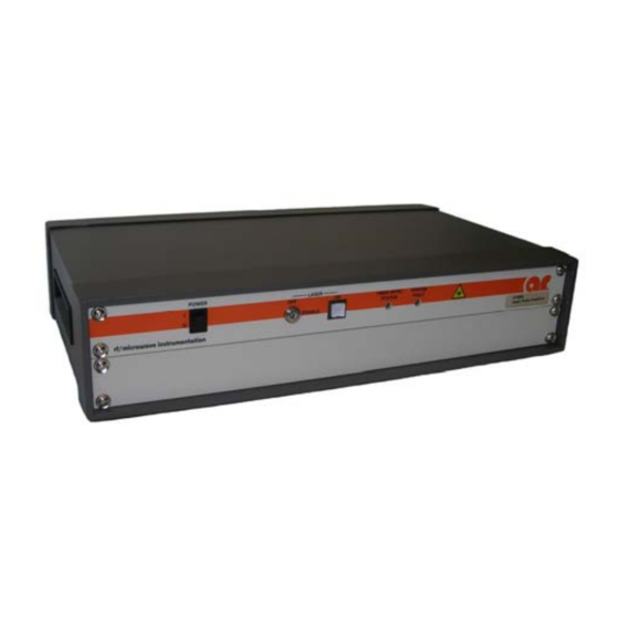
Figure 1-1. PL7004 Probe Figure 1-2. FI7000 Interface SUGGESTED APPLICATIONS • EMC field monitoring • Electric field mapping SPECIFICATIONS Refer to the AR Specification sheets at the end of this section for detailed specifications of the kit, probe, and interface. Rev F... -
Page 18: Accessories
PL7004 Kit ACCESSORIES AR offers a number of accessories for use with this probe kit. • PS1000 probe stand, non conductive • FM7004 Field Monitor. • Long fiber optic cables for single length up to 100 m • Bulkhead fiber optic cable feed through adapters (sets of two). - Page 19 Specifications Features The PL7004/Kit includes the equipment listed below. The FI7000 is housed in a 19” wide by PL7004/Kit 3.5” (2U) high instrument case with a 1.75 (1U) high blank panel. Please see individual product specification sheets for details. Peak Measuring Electric...
- Page 21 FI7000 in 20 msec. quencies. When correction The PL7004 extends the range of AR laser pow- factors are applied, the true ered E–field probes to use in measuring peak accuracy of the probe can be pulsed electric fields.
- Page 22 1 millisecond pulse period (1kHz pulse rate, 1% duty): ±0.5 dB/–1.0 dB typical To order AR Products, call 215.723.8181. For an applications engineer call:800.933.8181. Direct to Service call: 215.723.0275 or email: service@arworld.us For Faxing Orders:866.859.0582 (Orders Only Please) info@arworld.us...
- Page 23 160 School House Rd Souderton, PA 18964 215-723-8181 For an applications engi- neer call:800.933.8181 To order AR Products, call 215.723.8181. For an applications engineer call:800.933.8181. Direct to Service call: 215.723.0275 or email: service@arworld.us For Faxing Orders:866.859.0582 (Orders Only Please) info@arworld.us www.arworld.us...
-
Page 25: Theory Of Operation
DESIGN OF THE PROBE KIT The Model PL7004 Probe Kit consists of two principal functional units: the probe and the probe interface. The two units are connected by two pairs of fiber optic (F/O) cables. Power to operate the probe and commands to the probe are provided from the interface on one of the F/O cables. -
Page 26: Optical Receiver/Power Supply
PL7004 Kit 2.2.4 Optical Receiver/Power Supply The probe is powered optically. The laser light is fiber-optically transmitted to the probe. The laser light is received via an efficient photon (light) power to electrical power converter. The electrical DC power is then regulated, split, re-regulated and distributed to power the probe. -
Page 27: Interfaces (Ieee, Rs-232, F/O Rs-232, Usb)
PL7004 Kit 2.3.4 Interfaces (IEEE, RS-232, F/O RS-232, USB) Refer to specific probe kit specifications interfaces to a host. All interfaces are controlled by the control logic 2.3.5 Control Logic The control logic provides operational control and routing of signals. It includes a microcontroller. It functions to route the host commands, received from one specific controller/host interface, forward to the probe, and to route the probe responses backward to the same controller/host interface. - Page 28 PL7004 Kit Rev F...
-
Page 29: Operation
3. OPERATION WARNINGS AND CAUTIONS Throughout this manual, the symbol: WARNING: indicates that a hazard exists that may result in personal injury or loss of life. CAUTION: indicates that failure to follow procedures may result in damage to the equipment. WARNING: DANGER - High Voltage Present: The probe interface assembly operates from AC line voltages which may present a shock hazard. -
Page 30: General Guidelines For Use Of Field Probes
A/D conversion and smoothing times. This time is not transmission speed dependent. [This time is field level dependent in certain AR probes, a longer time at low levels. The shortest time is in the sub ms range, longest in the 50 ms range, though it may be extended on some models to improve sensitivity.]... -
Page 31: Guidelines For Use Of Field Probes
PL7004 Kit Axis Offset The location of the center of each sensor element of three axis (X,Y,Z) field sensors is commonly not at a single point in space. This fundamentally has to do with the physical constraints of mounting more that one thing, a sensor and diode, in the same space plus other considerations related to a specific probe design. - Page 32 PL7004 Kit 3.3.2.5 Out-of-Band Response and In-Band Response Considerations Although the specified operating frequency range of a probe may be limited, probes typically respond to signals both above and below their specified frequencies. Users should be alert to unexplained readings that may be caused by unintended fields.
-
Page 33: Probe Kit Appearance And Features
Repositioning the probe to adjust for the individual offset of each axis may produce a more consistent result. PROBE KIT APPEARANCE AND FEATURES 3.4.1 PL7004 Probe Figure 3-1: PL7004 Probe Features Table 3-1. PL7004 Probe Features Label Title Function Sensor elements Three antennas sensor elements to sense electric field. -
Page 34: Probe Interface
PL7004 Kit 3.4.2 Probe Interface The Power switch on the interface activates the interface (ON) and deactivates the interface and probe (OFF). A separate key on the interface enables the laser. A momentary switch initiates the laser on sequence. If the fiber optic cables are not sensed or the probe does not respond within a preset time –... -
Page 35: Installation
PL7004 Kit Figure 3-4. Interface Assembly Label Details INSTALLATION 3.5.1 Unpacking Upon receiving the probe kit, inspect the shipping container for obvious signs of external damage. If damage is observed, notify the carrier and contact an authorized service representative. Unpacking: 1. -
Page 36: Cooling Requirements
PL7004 Kit 3.5.2.2 Probe The probe is designed to be mounted on a non-conductive (dielectric) probe stand. The stand should be supplied with a 1/4-20 non-conducting (dielectric) screw with 1/8 to 1/4 inch thread extending beyond the mounting surface. The probe has two permanently attached short fiber optic cables. Do not attempt to pull on these cables. -
Page 37: Ac Line Power Connection
PL7004 Kit 3.5.4 AC Line Power Connection AC line power connection to the probe interface is made at the AC inlet, which is a female IEC-320 connector. A line cord suitable for the type of AC outlet used, and consistent with local electrical codes, must be obtained to mate with this connector. -
Page 38: Rs-232 Operating Protocols
PL7004 Kit 3.7.1 RS-232 Operating Protocols 3.7.1.1 Normal Operation Command/Response This section lists the operating protocols RS-232 on the interface for normal operation. Communication Protocol Data Type: RS-232 Serial Data mode: Asynchronous Word Length: 8 bit Parity: None Stop Bits:... - Page 39 PL7004 Kit If a command is of a type that does not require the probe kit to return any data, the probe responds as above, but with no data field. If a recognizable error occurs, the probe kit responds with an error code, as detailed in 3.7.1.2.
- Page 40 PL7004 Kit Command To Probe Kit Response From Probe Kit Read Probe Axis Data (X, Probe kit response structure: <start character><command letter><x Y, & Z only) axis field value ><y axis field value>< z axis field value><status A<CR> flag><termination> :A<x><y><z><s><termination>...
- Page 41 <f>,<m>,<r><termination> where: , = Separator character ASCII comma f = manufacturer, AR or AR WORLDWIDE (1 to 18 characters) m = Interface model designation (1-6 characters) r = Firmware revision level (0-10 characters) termination = Depends on the selected response termination...
- Page 42 PL7004 Kit Command To Probe Kit Response From Probe Kit Set Response Termination Where: Character(s) n = 0 to 3 TERMn<CR> 0 = <LF><CR> factory default (for compatibility with legacy control software) 1 = <CR><LF> 2 = <LF> 3 = <CR>...
-
Page 43: Gpib (Ieee-488) Operating Protocols
PL7004 Kit Code Command Detail command strings are fully sent with less than 5 seconds between each character.] Ed<termination> Buffer full error Too many characters contained between the Start Character and the Carriage Return of a command. Message is not processed by the probe kit. -
Page 44: Usb Operating Protocols
Automation Explorer or LabView. If a user wishes to write code in a different programming language, a custom driver can be requested from AR. It should be noted that the USBTMC driver provided by National Instruments is a VISA driver which can be used with other programming languages besides LabView. For more information on this please consult the National Instruments Website found at www.ni.com. -
Page 45: F/O Serial
PL7004 Kit 3.7.3.1 Normal Operation Command/Response Uses the Normal Operation Command/Response as defined for RS-232. 3.7.3.2 Error Code Responses Uses the Error Code Responses as defined for RS-232. 3.7.4 F/O Serial Dedicated port for connection to FM7004 monitor. Rev F... - Page 46 PL7004 Kit Rev F...
-
Page 47: Maintenance
In the event that the kit malfunctions while it is still under warranty, always contact an authorized service representative. Contact AR Customer Service for return authorization before returning any part of the probe kit for repair or replacement. PREVENTIVE MAINTENANCE The probe kit has been calibrated at the factory and should maintain its calibration for a long period of time if not physically abused. -
Page 48: Cables
Prior to returning a probe kit for calibration, the user should specify what type of calibration is requested, standard or custom, and request a quote for the calibration. User can specify normal AR calibration (standard) Rev F... -
Page 49: Upgrade Policies
If not otherwise specified by the user in the calibration order, AR will verify that the probe kit is performing within specifications by performing a subset of testing equivalent to the test performed on this unit when shipped. - Page 50 PL7004 Kit Rev F...
-
Page 51: Appendix A: Dimensional Drawings
Appendix A: Dimensional Drawings Figure A-1. Model PL7004 Rev F... - Page 52 PL7004 Kit Rev F...
- Page 53 These modules are not field-repairable and should never be opened outside of AR’s Microelectronics Lab. The modules in these product lines have a security label on two sides of the modules between the housing and lid/cover. If the security label is removed and or cut, the warranty of the module will be voided.
Need help?
Do you have a question about the PL7004 and is the answer not in the manual?
Questions and answers