Table of Contents
Advertisement
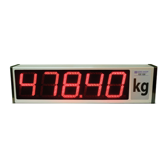
This high intensity LED display off ers a
fl exible solution for a variety of high-
speed, high accuracy weighing, batching
and level measurement operations.
It features two isolated auto-detecting
serial ports, and accepts serial inputs
from a wide range of devices.
Features
›
Isolated RS232 or RS485/422 serial
inputs, counter input
›
Auto detecting software for pairing
instrument, or can be manually set
›
3 x 5A relays for stop/go lights or
centre of zero light
›
Intuitive text prompts for easy setup
›
Display in kg, g, t, lb, N - any units
›
Very high thermal stability
›
Remote inputs (external devices)
›
Customisable inputs to suit your ap-
plication
Copyright © 2014 Gedge Systems
High Intensity LED Large Display
Optional
›
4, 5 or 6 digit annunciators
›
Red and green traffic control lights
›
Annunciators for centre of zero,
motion, and nett
›
Double sided display
›
Mounting kits (wall or pole)
›
Weather proof hoods
Contents
1 - Order Codes ............................... 2
2 - Specifi cations ............................... 3
3 - Casing & Display ........................ 4
4 - Wiring ......................................... 6
6 - Confi guration Menu (F2) ............ 9
Appendices ...................................... 19
GS120
GS120-MAN-14V05 (0307)
1
Advertisement
Table of Contents

Summary of Contents for Gedge Systems GS120
-
Page 1: Table Of Contents
Display in kg, g, t, lb, N - any units 6 - Confi guration Menu (F2) .... 9 › Very high thermal stability › Remote inputs (external devices) Appendices ........19 › Customisable inputs to suit your ap- plication Copyright © 2014 Gedge Systems GS120-MAN-14V05 (0307) -
Page 2: Order Codes
ORDER CODES Signal input (Select one) GS120–232– GS120 LED large display with RS232 signal input GS120–485– GS120 LED large display with RS485 signal input GS120–422– GS120 LED large display with RS422 signal input GS120–CL– GS120 LED large display with 20mA current loop input... -
Page 3: Specifications
Enclosure rating IP65 Enclosure construction Anodized aluminium with toughened glass Viewing angle 120° Viewing range 120m – Ambient temperature 10– 65°C Ambient humidity 5–95% Character format All standard ASCII characters Shipping weight 14.6kg Copyright © 2014 Gedge Systems GS120-MAN-14V05 (0307) -
Page 4: Casing & Display
CASING & DISPLAY 3.1 - Case dimensions Dimensions (in mm) 4 Digits 5 Digits 6 Digits 7 Digits 8 Digits 1028 GS120-MAN-14V05 (0307) Copyright © 2014 Gedge Systems... - Page 5 Setup menu (Section 5). Used to access the Confi guration menu (Section 6). Used to save your settings and advance to the next step in the process. Used to scroll through options and increase/decrease values. Copyright © 2014 Gedge Systems GS120-MAN-14V05 (0307)
-
Page 6: Wiring
BEFORE YOU BEGIN WIRING, ensure that the unit is switched off and the power supply is disconnected. 4.1 - Basic wiring Power input User input Auxiliary I/O Com 2 Analog O/P RS232 RS485 Relay output Primary serial port (Com 1) GS120–232/485/422 GS120–CL GS120-MAN-14V05 (0307) Copyright © 2014 Gedge Systems... - Page 7 4.2 - Wiring the user inputs for use as counters GS120 user inputs can be confi gured to run in counter mode. To enable the counter mode options, User input 1 must fi rst be set to Counter (see 6.4B). User input 1 is always used as the count pulse input.
-
Page 8: Quick Input Setup Menu (F1)
A&D Mercury inputs. (This includes baud rates between 600 and 19200 baud, data bits and stop bits.) Auto 2 will automatically detect all Auto 1 inputs, as well as GSE, Schenck, Sartorious, Soehnle, Flintab, Condec, and Eagle inputs. GS120-MAN-14V05 (0307) Copyright © 2014 Gedge Systems... -
Page 9: Configuration Menu (F2)
If you selected –UserIP–, proceed to section 6.4 now. If you selected –AnlgOP–, proceed to section 6.5 now. If you selected –Exit–, the unit will return to normal operating mode. Copyright © 2014 Gedge Systems GS120-MAN-14V05 (0307) -
Page 10: Input Setup
2nd character from end Disabled 3rd character from end Count from end character back to start of weight string Com timeout in seconds Communication settings Baud rate Auto Parity Manual Data bits Stop bits GS120-MAN-14V05 (0307) Copyright © 2014 Gedge Systems... - Page 11 2 (auxiliary I/O), and then press _ _ Input limit scrolls across the bottom row and the current input limit appears in the top row (default 999999). If the input exceeds this limit, the GS120 will show OVER. Adjust this value using the...
- Page 12 Use the buttons to set the count from the end character to the start of the weight string: either a number from 1–40, or Ignore. Then press GS120-MAN-14V05 (0307) Copyright © 2014 Gedge Systems...
- Page 13 This parameter relates to the output rate of the device driving the GS120. If the GS120 has not received an output string from the external device within the specifi ed time, it will treat this as an error and the display will change to show that it has lost communications.
-
Page 14: Display Setup
If you select a unit, a single character unit (K, t or L) will be displayed in the right-hand digit of the GS120. This feature does not perform any conversion calculations. _ _ Brightness scrolls across the bottom row, and the current display brightness appears in the top row. - Page 15 None, StartLED, StopLED, Strt/Stp Strt/Stp, Rst Cnt Note that StartLED, StopLED and Strt/Stp functions can only be used for GS120 display models with a red/green traffi c light segment installed. Counter functions (including Gate Count, Count Direction and Reset Count) are only available if Counter is selected as your User 1 input function in 6.4B (see 4.2 for...
- Page 16 Relays or mechanical switches will oft en exhibit contact 'bounce' when the contacts open or close, which may cause false count pulses to be registered. In debounced counter mode, the GS120 will only accept an input pulse as valid if it remains active for 20ms or more. This limits the maximum frequency to 25Hz.
- Page 17 If you selected Yes, connect a mA or volt meter across the analogue out- put connector (see section 4), and then continue to 6.5E. If you selected No, skip to 6.5G now. Copyright © 2014 Gedge Systems GS120-MAN-14V05 (0307)
- Page 18 – AnlgOP – appears in the top row, and _ _ Edit function scrolls across the bot- tom row. You are now back at 6.1C, and may select a new function to edit. GS120-MAN-14V05 (0307) Copyright © 2014 Gedge Systems...
-
Page 19: Appendices
Com 1 string (if the display options are set to use decimal point and/or units information from the incoming strings). Care should be taken in Summing mode to ensure that both weighing instruments are outputting the same meas- urement scale. Copyright © 2014 Gedge Systems GS120-MAN-14V05 (0307) - Page 20 APPENDIX B - LAST RESORT The last resort option can be used when trying to connect the GS120 with an instru- ment which is not included in the device type list, or one which is using a custom output string.
- Page 21 In this case, the 3rd to last, 2nd to last and/or end character may be specifi ed. Any/all of these characters may be set to Ignore if they are not fi xed. The GS120 will check that all three end characters match their values (if speci- fi ed), before the string is accepted.
- Page 22 The GS120 will then treat this as the fi rst (or last) character, and ignore any un- wanted characters before (or aft er) it. As long as the distance between this char- acter and the weight string remains constant, the string will still be accepted.
- Page 23 GS120 user inputs can be confi gured as Start/Stop controls for the traffi c light seg- ment, or as counter controls (if the GS120 is confi gured to run in counter mode). To enable counter mode options, User input 1 must fi rst be set to Counter in 6.4B (see 4.2 for more information on counter mode).
- Page 24 Both Com 1 and Com 2 must be set to Disabled in 6.2D. The Com 2 port can then be used to connect the GS120 to your PC or PLC device. Com 2 will revert to a simple ASCII mode operating at 115,200 baud, 8 data bits, no parity, 1 stop bit.
- Page 25 Text strings cannot be greater than 100 characters in length. The GS120 has a 7 segment display designed for numeric digits. Because of this, some alphabet and special characters are diffi cult to display, and a combination of upper and lower case letters are used.
- Page 26 GS120-MAN-14V05 (0307) Copyright © 2014 Gedge Systems...
- Page 27 Copyright © 2014 Gedge Systems GS120-MAN-14V05 (0307)
- Page 28 Gedge Systems 27 Rhur Street, Dandenong South, VIC 3175, Australia Ph: +61 (3) 9791-8944 | Fax: +61 (3) 9791-8804 info@gedgesystems.com.au www.gedgesystems.com.au GS120 MV1.26 Document Revision Code: GS120-MAN-14V05 Date Code: 140307...
Need help?
Do you have a question about the GS120 and is the answer not in the manual?
Questions and answers