
Subscribe to Our Youtube Channel
Summary of Contents for Omnitracs Trailer Tracks 150
- Page 1 Trailer Tracks 150 Installation and Troubleshooting Guide 80-J7616-1 Rev. C July 2017 80-J7616-1 Rev. C MAY CONTAIN U.S. AND INTERNATIONAL EXPORT CONTROLLED INFORMATION...
- Page 2 Dallas, TX 75201 U.S.A. © 2016-2017 Omnitracs, LLC. All rights reserved. Omnitracs is a trademark of Omnitracs, LLC. All other trademarks are the property of their respective owners. Omnitracs endeavors to ensure that the information in this document is correct and fairly stated, but Omnitracs is not liable for any errors or omissions.
-
Page 3: Table Of Contents
TT150 Terminal ........................9 TT150 Power Cable Assembly .................... 9 TT150 Installation Kit ......................10 General Wiring Guidelines ....................11 Making Electrical Connections ....................11 Approved Omnitracs Electrical Connectors ................11 Wire Stripping ........................11 Butt Splicing ........................11 Crimping ..........................12 Strain Relief ........................13 If there is NOT sufficient wire available for the Four-Finger Wrap Method: .......14 Ring Terminals ........................14... - Page 4 FCC/IC Compliance Statement ..................16 Caution ..........................16 General Installation Information ....................16 Verify the Trailer Is in Good Condition ................16 Survey the Trailer .......................17 Terminal and Cables ......................17 What to Consider Before Installing the System ..............17 Installation Guidelines ......................17 Typical TT150 Installation Sequence ..................18 Tools and Supplies Needed for Installation ................18 Installing the TT150 Terminal .....................19 Dry Van Trailers ........................19...
- Page 5 TT150 Status LEDs are Off ....................32 Problem: TT150 Status LEDs are Off ..................32 GPS Status LED Blinking ....................34 Problem: Green GPS LED Blinking ..................34 Communication Status LED Blinking ................35 Problem: Orange Communication LED Blinking ..............35 Battery Problem ......................37 Problem: Low Battery Message .....................37 TT150 System Uninstallation ..................38 Before Uninstall ........................38 TT150 System Removal ......................38...
- Page 6 TT150 Device Diagnostics....................50 Set the Trailer ID and SCAC ....................50 Uninstall a Device from a Trailer..................51 Facilitate an RMA .......................52 Set Trailer Mileage ......................52 80-J7616-1 Rev. C MAY CONTAIN U.S. AND INTERNATIONAL EXPORT CONTROLLED INFORMATION...
-
Page 7: How The Trailer Tracks Service Works
1) How the Trailer Tracks Service Works Introduction The Trailer Tracks service is the Omnitracs wireless system for identifying and locating trailers for the trucking industry. This service provides cost-effective status monitoring and management of trailers. The TT150 system sends status information over-the-air (OTA) to the customer using cellular functionality. -
Page 8: What Is The Trailer Tracks Service
the NOC. After the NOC receives the information, it sends the information to the Trailer Tracks Web Portal. The GPS satellite constellation is used for location determination. What is the Trailer Tracks Service? The Trailer Tracks service is networking technology and hardware components installed on a customer’s trailer. -
Page 9: Tt150 System Component Overview
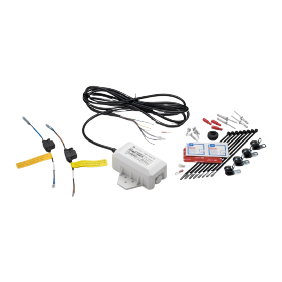
2) TT150 System Component Overview TT150 Components TT150 Terminal TT150 terminal with microprocessor, cellular modem, rechargeable internal battery pack, cellular antenna, and GPS antenna. Attached to the terminal is a cable for recharging the TT150 battery pack when the trailer is connected to a tractor. The terminal is designed according to industry environmental specifications. -
Page 10: Tt150 Installation Kit
TT150 Installation Kit The TT150 installation kit contains an assortment of items that can be used for a myriad of installation configurations based on your needs. • 2 non-duraplate rivets, used for securing the TT150 terminal on most dry-van trailers •... -
Page 11: General Wiring Guidelines
3) General Wiring Guidelines Making Electrical Connections Approved Omnitracs Electrical Connectors The only Omnitracs-approved electrical connectors are crimp butt splices and crimp ring terminals. Omnitracs recommends Nylon insulated, seamless butt connectors with inspection windows. Heat-shrinkable butt connectors are preferred. When butt splicing multiple wires on one end of a butt splice and a different number of wires on the other end, step-down butt splices are recommended. -
Page 12: Crimping
2. Repeat this process for the wire on the opposite end of the butt splice. Once a proper butt splice is confirmed, it is important to properly crimp the butt splice to hold the connection. Crimping • When crimping a butt-spliced wire or cable, be sure the insulated butt splice is crimped using the insulated position on the crimp tool and not the crimping “tooth”... -
Page 13: Strain Relief
3. Verify that the crimps are good and the wires have not been damaged. 4. Do a pull test. Pull on both ends of the wires to ensure a solid butt-spliced connection exists. The crimped butt splice securely grips the insulated wires. Strain Relief If there is sufficient wire available for the Four-Finger Wrap Method: 1. -
Page 14: If There Is Not Sufficient Wire Available For The Four-Finger Wrap Method
5. Firmly tug on the butt-spliced wire connection to make sure the tie wraps do not pull loose. If there is NOT sufficient wire available for the Four-Finger Wrap Method: 1. Securely tie wrap the butt spliced wires to existing wires or harnesses in the nearby vicinity. -
Page 15: Routing And Protecting Cables
If grounding terminals are not available, remove the paint from the surface of the metal connected to the chassis to make the ground. Make sure the wires are not strained or vulnerable to damage. Routing and Protecting Cables Cable Routing Guidelines •... -
Page 16: Tt150 Installation Planning
4) TT150 Installation Planning Important Notes Refer to Chapter 3: General Wiring Guidelines, while planning your installation. The cable chapter provides specific information on cables and wiring and should be considered during the installation planning stage. Installers should be familiar with basic automotive wiring. Regulatory Compliance Information FCC/IC Compliance Statement This device complies with part 15 of the FCC Rules. -
Page 17: Survey The Trailer
What to Consider Before Installing the System • Drill holes only when necessary. • Omnitracs recommends you use existing holes on the trailer for cable routing whenever possible. • Use silicone (RTV) sealant when necessary to prevent leakage. Installation Guidelines When making installation decisions, consider safety, security, quality and reliability, and accessibility. -
Page 18: Typical Tt150 Installation Sequence
Typical TT150 Installation Sequence Trailers and flatbeds often differ from manufacturer to manufacturer. The TT150 system was designed to work with a variety of trailer types; however, every installation is unique and should be thoroughly planned out before implementation. 1. Identify the installation location. 2. -
Page 19: Installing The Tt150 Terminal
5) Installing the TT150 Terminal Dry Van Trailers Overview The TT150 terminal installs outside the trailer. For dry van trailers, the TT150 terminal is installed on the trailer’s nose surface. The attached TT150 power cable runs from the TT150 terminal to the 7-way receptacle, which recharges the internal battery when a truck is connected to the trailer. - Page 20 1. On the outside of the trailer, select the location where the TT150 terminal will be installed/mounted. 2. Use the TT150 terminal as a template for marking the two holes needed for the rivets to mount the device. Use the holes on the outside of the mounting ears to allow access for a rivet gun.
-
Page 21: Tanker Trailers
Tanker Trailers Overview The TT150 terminal installs outside the trailer. For tanker trailers, the TT150 terminal is usually installed on the tank’s nose surface, near the 7-way. The attached TT150 power cable runs from the TT150 terminal to the 7-way receptacle, which recharges the internal battery when a truck is connected to the trailer. -
Page 22: Flatbed Trailers
Flatbed Trailers Overview The TT150 terminal installs on the bulkhead (if present) or frame rail. The attached TT150 power cable runs from the TT150 terminal to the 7-way receptacle, which recharges the internal battery when a truck is connected to the trailer. If the flatbed trailer has a watertight 7-way wiring harness junction box between the frame rails or three quarters of the way back, the power cable can also be connected there to allow for more potential mounting locations. - Page 23 3. Drill the two holes where marked using a 3/16” drill bit. 4. Place a dab of silicone sealant around each hole. 5. Using the appropriate supplied rivets, rivet the TT150 terminal to the trailer. Note: Non-duraplate rivets are used for walls with a thickness of .214 to .437 inch. Duraplate rivets are used for walls with a thickness of .35 to .625 inch.
-
Page 24: Connecting The Tt150 To The 7-Way
6) Connecting the TT150 to the 7-Way Overview The power cable is 10 feet long and can be cut as needed depending on the where the TT150 terminal is installed. Whenever possible, use existing holes to route cable into the 7-way. It may be necessary to drill a hole through the 7-way housing to provide a route for the cable. -
Page 25: Wire Connections At The 7-Way Receptacle
Wire Connections at the 7-Way Receptacle 1. Attach a fuse holder with a 3 amp fuse (provided) to the blue POWER wire on the TT150 system power cable using the attached butt splice. (Fuse holder supplied in the installation kit, marked with blue tape.) a. - Page 26 8. Use silicone (RTV) around the 7-way to prevent water intrusion. 9. Perform system verification and configure the TT150 using the Field Service Tool. See Chapter 7: System Verification. 80-J7616-1 Rev. C MAY CONTAIN U.S. AND INTERNATIONAL EXPORT CONTROLLED INFORMATION...
-
Page 27: System Verification
Note: When powering up a TT150 terminal for the first time, it is important that the TT150 terminal gets steady power for more than three minutes for it to establish a connection to the Omnitracs network. 2. Check the Communication and GPS LEDs to confirm the device is able to communicate and get a GPS fix. - Page 28 GPS LED (Green) Status LED Lighting GPS Off GPS On Slow blinking GPS Time Sync Fast blinking GPS Fix Alternates from solid to fast blink Communication LED (Orange) Status LED Lighting Modem Off Searching Slow blinking Network Available Fast blinking Registered but no inbound Alternates from solid to fast blink acknowledgment...
-
Page 29: Using The Tt150 Fst
Using the TT150 FST 1. Log into the TT150 FST at https://services.omnitracs.com 2. Enter the TT150 device’s serial number manually or by scanning the serial number on the TT150’s label. Shows Company ID the TT150 device belongs to, the SCAC, and the Trailer... -
Page 30: Tt150 Configuration
TT150 Configuration 1. Tap the pencil icon in Device Assignment. a. Enter the new Trailer ID b. Confirm the trailer is assigned to the correct SCAC c. Tap Initial Installation as the reason d. Tap Save. 2. Optional - Tap the Misc button in Actions. a. -
Page 31: System Verification Form
7-Way Power On: No Record Voltage: Phone Signal Strength: Number of Bars: Notes Checkout Completed Signature: Date: Time: If you have any questions, contact Omnitracs Customer Support at 800-541-7490. 80-J7616-1 Rev. C MAY CONTAIN U.S. AND INTERNATIONAL EXPORT CONTROLLED INFORMATION... -
Page 32: Tt150 Status Leds Are Off
8) TT150 Status LEDs are Off Problem: TT150 Status LEDs are Off Both LEDs should be lit and solid when the trailer’s 7-way is receiving power. If both LEDs are off, this indicates one of two possible conditions: • The LEDs have been disabled via the Trailer Tracks Portal or the TT150 FST. Change the setting if needed. - Page 33 2. If power is confirmed to be provided by the 7-way connection, confirm the fuses on the TT150 blue and brown wires are good. 3. If the fuses are good, verify each of the TT150 power cable connections at the trailer’s 7- way (white ground lead, blue fused power lead, and brown fused lights lead).
-
Page 34: Gps Status Led Blinking
9) GPS Status LED Blinking Problem: Green GPS LED Blinking If the Green GPS LED continues to blink (slow or fast), the TT150 terminal is not able to receive signals from GPS satellites. If this condition persists, it’s likely there is a metal obstruction blocking the GPS signals. -
Page 35: Communication Status Led Blinking
If the Orange COMM LED continues to blink fast (1 blink per second), this indicates the trailer is in cellular coverage but the Omnitracs network server is not responding. This could be a temporary condition – possibly during a system maintenance window. If the condition persists, call the Omnitracs Hotline at 800-541-7490 to check the terminal’s provisioning status and... - Page 36 • The Omnitracs network server is not responding. This could be a temporary condition, possibly during a system maintenance window. If the condition persists, call the Omnitracs Hotline at 800-541-7490 to check the terminal’s provisioning status and TT150 system availability.
-
Page 37: Battery Problem
11) Battery Problem Problem: Low Battery Message The FST and the Trailer Tracks Portal display the internal lithium ion battery voltage each time the TT150 communicates. When a TT150 terminal is shipped from the factory, the battery is charged to roughly 3.8 volts, which is the optimum level for shelf storage. -
Page 38: Tt150 System Uninstallation
12) TT150 System Uninstallation Before Uninstall If you intend to reinstall the TT150 on a different trailer later (instead of a scrap or RMA) and the terminal is in good shape, then refer to Appendix C: Component Information to order the appropriate rivets or VHB tape. -
Page 39: Periodic System Maintenance
13) Periodic System Maintenance Important TT150 system maintenance should be done at least once a year. Preferably, each time preventative maintenance is done, the following should also occur: • Inspect all mounts to ensure fasteners are in place • Inspect the trailer 7-way harness to ensure that the TT150 connection is solid and the fuses are not burnt out •... -
Page 40: Appendix A: Tt150 Power Cable
Appendix A: TT150 Power Cable This illustrations shows the various cable assemblies. Note: The yellow and green are used for engineering purposes only, they should be taped apart from each other when installation is performed. 80-J7616-1 Rev. C MAY CONTAIN U.S. AND INTERNATIONAL EXPORT CONTROLLED INFORMATION... -
Page 41: Appendix B: Tt150 System Specifications
Appendix B: TT150 System Specifications TT150 System Terminal Parameters TT150 System Terminal Input/Output Parameter Signal Type Specifications Characteristics Input voltage 9 VDC to 18 VDC Meets SAE-J1113-11 for 12 VDC systems Current draw from tractor power (12 VDC) ON—Receive mode Current <100mA ON—Transmit mode... -
Page 42: Appendix C: Component Information
Appendix C: Component Information This appendix provides material control numbers (MCNs) for the different TT150 system components referred to in this guide or considered additional useful information. TT150 System Component Material Control Numbers System Component Latest MCN TT150 System Terminal Master Packs 7-way power master pack 65-J8163-1 TT150 Install Kit... -
Page 43: Appendix D: Trailer 7-Way Configurations
Appendix D: Trailer 7-way Configurations This appendix describes four different trailer 7-way configurations that may be encountered. • Slip-on with circuit breaker • Terminal lug with circuit breaker • Slip-on without circuit breaker • Terminal lug without circuit breaker 7-way Conductor Electrical Connector Overview SAE J560 Seven Conductor Electrical Connector Conductor Conductor Identification... -
Page 44: 7-Ways With Circuit Breakers
7-ways with Circuit Breakers Connect to the unprotected (truck) side of the 7-way circuit breaker which can be verified by doing a visual inspection. The unprotected side is the side of the breaker without the blue wire connected. Caution: When working with a slip-on 7-way, always install the TT150 system on unprotected (truck) side of the trailer. -
Page 45: 7-Ways Without Circuit Breakers
7-ways Without Circuit Breakers The following 7-way does not have circuit breaker protection. The TT150 system can be connected to the appropriate 7-way slip-on connector. 80-J7616-1 Rev. C MAY CONTAIN U.S. AND INTERNATIONAL EXPORT CONTROLLED INFORMATION... - Page 46 The following 7-way does not have circuit breaker protection. The TT150 system can be connected to the appropriate 7-way terminal studs. 80-J7616-1 Rev. C MAY CONTAIN U.S. AND INTERNATIONAL EXPORT CONTROLLED INFORMATION...
-
Page 47: Appendix E: Tt150 Field Service Tool
FST to view their company’s devices or, if a 3rd party installer, the devices of the company they are installing for. Companies that use 3rd party installers such as Omnitracs licensed Service Centers or OEM installers must have access enabled for 3rd party installers. If this access is not enabled, only installers in the company’s account can access its devices in the FST. -
Page 48: Accessing The Fst From A Mobile Device
Accessing the FST from a Mobile Device 1. Using an Android or Apple mobile device with internet connectivity, open https://services.omnitracs.com in a Google Chrome or Apple Safari web browser. 2. Enter your Company ID. 3. Enter your User ID. 4. Enter your Password. -
Page 49: Accessing The Fst From A Pc Or Laptop
Accessing the FST from a PC or Laptop 1. Using a pc or laptop with internet connectivity, open https://services.omnitracs.com in a Firefox, Google Chrome, Apple Safari, Microsoft Edge, or Internet Explorer 10 or 11 web browser. 2. Enter your Company ID. -
Page 50: Tt150 Device Diagnostics
Version information shows the current script and firmware on the TT150 device. This information may be needed by Omnitracs support personnel for troubleshooting purposes. Actions allows a user to turn the TT150 device’s LED lights on or off, pull up a legend of... -
Page 51: Uninstall A Device From A Trailer
Note: When entering the new trailer ID number, avoid entering an erroneous character or blank space in the first digit as this will create an invalid trailer record. The first digit of the trailer ID number must contain a valid character. 3. -
Page 52: Facilitate An Rma
Facilitate an RMA If you must RMA a TT150 device, you will need to assign the new device to the trailer when you receive it. Instead of having to first unassign a TT150 device then assign the replacement device, the process is simplified for RMAs. When you receive the replacement TT150 device, follow the normal installation steps.
Need help?
Do you have a question about the Trailer Tracks 150 and is the answer not in the manual?
Questions and answers