Table of Contents
Advertisement
Advertisement
Table of Contents

Subscribe to Our Youtube Channel
Related Manuals for MAXPhotonics MFS Series

Summary of Contents for MAXPhotonics MFS Series
- Page 1 MFS Series - M BOX Maxphotonics Co.,Ltd.
- Page 2 Copyright Notation Copyright © Maxphotonics Co ., Ltd ( here after referred to as Maxphotonics). All rights reserved. You may not copy, modify, transmit or publish this publication, in any form, in any media or by any means, without the prior written permission of Maxphotonics, except as allowed under applicable copyright laws.
- Page 3 Preface Thank you for using the MFS Series pulsed fiber laser products. We compile this document for you in order that the laser is used and maintained properly. Due to the limited level of the writers, coupled with time constraints, there are some careless mistakes in this document,and your understanding will be much appreciated.
- Page 4 Company Profile Found in 2004, Maxphotonics is one of the first fiber laser manufacturers in China. It is also the first in China to realize independent intellectual property rights and vertical integration in the core technologies of fiber lasers and optical devices.
-
Page 5: Table Of Contents
CONTENT Chapter 1 Characteristic Description …………………………………… 5 Chapter 2 General Safety Information …………………………………… 6 1-Safety Conventions …………………………………………………………… 6 2-Laser Protection ……………………………………………………………… 7 3-General Safety Instructions ………………………………………………… 8 4-Additional Safety Information ……………………………………………… 11 Chapter 3 Product Description ……………………………………………… 12 1-Features ………………………………………………………………………… 12 2-Laser Model Designation Codes ……………………………………………... - Page 6 CONTENT Chapter 5 Using Instruction ………………………………………………… 17 1-Interface function description ……………………………………………… 17 2-DB 26 Pins Interface Definition ……………………………………………… 18 3-Button Function Description ………………………………………………… 23 4-Software operating manual ………………………………………………… 23 Chapter 6 Service and Maintenance ……………………………………… 24 1-Maintenance Notes …………………………………………………………… 24 2-Service Statements ……………………………………………………………...
-
Page 7: Chapter 1 Characteristic Description
Chapter 1 Characteristic Description MFS Series is one of the Maxphotonics outstanding products. Its appearance has revolutionary significance for the integration of high-speed and high- resolution laser marking system. Compact, stand-alone, easy-to-use design that can be integrated directly into the user's device. Low power consumption, practical and durable design for laboratory and market applications. -
Page 8: Chapter 2 General Safety Information
Chapter 2 General Safety Information 1-Safety Conventions All safety warning symbols during operating process of the laser include: SYMBOLS DESCRIPTION WARNING: Refers to a potential Electrical Hazard to human body. It requires a procedure that, if not correctly followed, may result in bodily harm to you and/or others. Do not proceed beyond the WARNING sign until you completely understand and meet the required conditions. -
Page 9: 2-Laser Protection
LaserVision USA, Kentek Corporation, Rochwell Laser Industries, etc. All the supplier information is provided by Maxphotonics only for the convenience to use, so Maxphotonics assumes no responsibility for any problem caused by using the products of... -
Page 10: 3-General Safety Instructions
Chapter 2 General Safety Information 3-General Safety Instructions In order to ensure the safe operation and optimal performance of the product, please follow these warning and cautions in additionto the other contained elsewhere in this document. 1.Specular Reflection There are often numerous secondary laser beams produced at various angles in the output port of the laser. - Page 11 Chapter 2 General Safety Information and wavelength range of the l aser. 4.Do not install collimators when the laser is active. 5.It is forbidden to turn on the laser during the mounting of fiber or cutting head. 6.For collimated outputs, maintaining a clean output lens is essential. Always close (re-cap) the collimator after use.
- Page 12 Chapter 2 General Safety Information and dust-free. 2.Before switching on the device make sure that environmental temperature and humidity are within a specified range. WARNING: ◎ Optical damage may result from failure to comply with the above instructions. Such damage is not covered by the warranty. 1.Avoid the impaction on the shipper rod of worktable when the laser is working.
-
Page 13: 4-Additional Safety Information
Chapter 2 General Safety Information 4-Additional Safety Information For additional information regarding Laser Safety, please refer to the list below: Laser Institute of America(LIA) 13501 Ingenuity Drive, Suite 128 Orlando,Florida 32826 Phone:407 380 1553,Fax: 407 380 5588 Toll Free:1 800 34 LASER American National Standards Institute ANSI Z136.1, American National Standard for the Safe Use of Lasers (Available through LIA) -
Page 14: Chapter 3 Product Description
Chapter 3 Product Description 1-Features MFS Series is one of the Maxphotonics outstanding products. Its appearance has revolutionary significance for the integration of high-speed and high- resolution laser marking system. Compact, stand-alone, easy-to-use design that can be integrated directly into the user's device. Low power consumption, practical and durable design for laboratory and market applications. -
Page 15: 3-Certification
Chapter 3 Product Description 3 - Certification Maxphotonics certifies that this equipment has been thoroughly tested and inspected and meets published specifications prior to shipping. Upon receiving your equipment, check whether the packaging and accessories have been damaged in transit. If damage is apparent, please contact Maxphotonics... -
Page 16: Chapter 4 Specification
Chapter 4 Specification 1-Characteristic Parameters Type MFS-10T MFS-20T Laser power 9±1W 19.5±0.5W Central wavelength 1064nm Beam quality M2 < 1.4 Frenquency tunable 20-50khz 30-60khz range Marking Area 110(F=160MM) (Standard) Engraving Line Speed 0-15000mm/s Mode for focusing Manual Marking Speed 600-1000 characters/min Min. -
Page 17: 2-Computer Configuration
Chapter 4 Specification 2-Computer Configuration TYPE Configuration Intel J1800 Processors Memory ADATA 4G DDR3L 1600 Ethernet 2x LAN Intel I211 (post IO interface) Graphic Intel® HD Graphics Control 1x HDMI:HDMI supported Max. resolution is 1920×1200@6 Display Port Hard disk 2x USB2.0;2x USB3.0 Interface 1x RS232(contact pin),and COM1 support mode RS422, Serial Port... -
Page 18: 3-Structural Layout
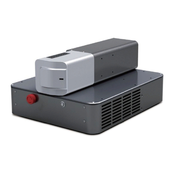
Chapter 4 Specification 3-Structural Layout Laser Views.(Unit:mm)... -
Page 19: Chapter 5 Using Instruction
ITEM User Manual and Test Power supply(optional) NOTE: ◎ If you find any damage to the outer packaging or internal components after receiving the products, please contact Maxphotonics or local representative immediately. 1-Interface function description Laser power supply as follows:... -
Page 20: 2-Db 26 Pins Interface Definition
Chapter 5 Using Instruction Definition of each interface: 1.Power Supply: 220V to 24V power adapter socket; 2.DB 15 Pins Interface:Scan head/Galvometer interface; 3.DB 26 Pins Interface:External Control IO interface of control card (more definition about IO); 4.USB Interface: For USB upgarde the control card program interface and WiFi interface;... - Page 21 Chapter 5 Using Instruction Item Direction COM Port Description EN_A_N input Differential Input Optical encoder input A- EN_B_N input Differential Input Optical encoder input B- Marking end pulse output, high MARKING_END output OUTIO_COM level available (around 4ms) IO_OUT1 output OUTIO_COM IO port output 1 OUTIO_COM input...
- Page 22 Chapter 5 Using Instruction 2.Rotary Port Item Direction COM Port Description Differential PULSE_P output Rotary motor pulse output + output Differential PULSE_N output Rotary motor pulse output - output Differential DIRECTION_P output Rotary motor direction output + output Differential DIRECTION_N output Rotary motor direction output - output...
- Page 23 Chapter 5 Using Instruction NOTE: ◎ Pull MARKING END, MARKING BUSY, MARKING ERR on three output ports to ensure pull-up current is higher than 40ma; If only for monitor the electrical level, then 10ma pull-up current will be ok; , if need to connect an electric relay, ensure the pull-up current is less than 40ma.
- Page 24 Chapter 5 Using Instruction NOTE: ◎ Pull up IO_OUT1,IO_OUT2 there output ports and make sure pull-up current below 40ma. Level Observation Point below than 10ma. If connect relay, please make sure current below 40ma. ◎ Do Level Observation at IO_OUT1,IO_OUT2 there ports, all observation point valid at high level.
-
Page 25: 3-Button Function Description
Chapter 5 Using Instruction 3-Button Function Description Definition of each interface function: 1.Emergency Stop button, press it, no laser emit; 2.Computer key switch. 4-Software operating manual Check the software operating instructions for details. -
Page 26: Chapter 6 Service And Maintenance
◎ For ensuring that the repairs or replacement within the warranty scope can be carried out, and perfectly maintaining your interests, please submit application to the Maxphotonics or the local representative after finding the faults. Upon receiving our authorization, you need to pack the product in a suitable package and return it. -
Page 27: 2-Service Statements
(4) Customer company name, address, contact person and contact number. Your problems will be follow-up by our technical support group after verified. If the problems cannot be solved , you may need to return the product to Maxphotonics for further troubleshooting. -
Page 28: Chapter 7 Warranty Statements
Warranty Statements 1-General Items Maxphotonics Co.,Ltd. carries out warranty for any defect of the product caused by its material and production technology within the warranty period agreed in contract, and ensures that its product meet the relevant quality and specification requirements specified in the document under normal use condition. - Page 29 IMPORTANT : ◎ Within the warranty scope, purchasers must feedback within 31 days after finding the product defect. ◎ Maxphotonics does not grant any Third Party rights to repair or replace the parts, the equipment or other Maxphotonics products.
Need help?
Do you have a question about the MFS Series and is the answer not in the manual?
Questions and answers