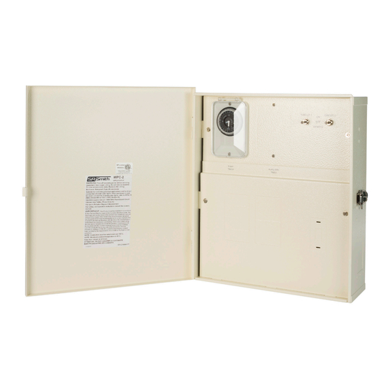
Table of Contents
Advertisement
Quick Links
WPC2-XXXX-T
Rated for use on 110/120VAC 60Hz and 220/240VAC 60Hz applications
4008814
ETL LISTED
Conforms to UL STD 379;
Certified to CSA STD C22.2 #218.1
Installation Instructions
Read these instructions in their entirety before performing any installation work
FOR USE WITH POOL AND SPA PRODUCTS
79-15224-00 REV C
Advertisement
Table of Contents

Summary of Contents for S.R.Smith WPC2 T Series
- Page 1 WPC2-XXXX-T Rated for use on 110/120VAC 60Hz and 220/240VAC 60Hz applications 4008814 ETL LISTED Conforms to UL STD 379; Certified to CSA STD C22.2 #218.1 Installation Instructions Read these instructions in their entirety before performing any installation work FOR USE WITH POOL AND SPA PRODUCTS 79-15224-00 REV C...
-
Page 3: Table Of Contents
Contents REPLACEMENT & ACCESSORY ITEMS......4 IMPORTANT SAFETY INFORMATION ......5 FCC WARNING . -
Page 4: Replacement & Accessory Items
R E P L A C E M E N T & A C C E S S O R Y I T E M S ITEM NO. QTY. PART # REPLACEMENT PART DESCRIPTION 42-15032-00 Timer 37-15000-00 Relay 94-15264-00 WPC Receiver, 2-circuit 94-15263-00 Remote Control 2-circuit (Transmitter) PLX-ANTKT-S... -
Page 5: Important Safety Information
I M P O R T A N T S A F E T Y I N F O R M A T I O N ELECTRICAL SHOCK HAZARD – SWITCH DOES NOT TURN OFF INPUT POWER. Failure to disconnect input power before servicing can lead to serious injury, or death. Disconnect input power before servicing. -
Page 6: Electrical Ratings
E L E C T R I C A L R A T I N G S Do not exceed the maximum electrical ratings of the WPC-2. A circuit breaker rated at 20Amps at 120VAC must be installed in the breaker panel to connect to the WPC-2 power input. Circuit 1 is rated for use of up to 2.5 amps @12VAC, and Circuit 2 is rated for use of up to 8 amps @ 120VAC. -
Page 7: Wiring Instructions
W I R I N G I N S T R U C T I O N S FOLLOW PROPER WIRING PRACTICES IN ACCORDANCE WITH ALL LOCAL REGULATORY REQUIREMENTS. IF USING WITH LOW VOLTAGE POOL LIGHTING, SEE PAGE 8 FOR ADDITIONAL REQUIRMENTS AND MATERIALS. -
Page 8: Hooking Up Low Voltage Lights To Circuit 1
H o o k i n g u p L o w V o l t a g e L i g h t s t o C i r c u i t 1 To connect a Low Voltage lighting product to Circuit 1 (12VAC), an NEC or local jurisdiction approved Pull / Junction / Bell Box must be used to directly connect the conduit from the lighting product, in line with the WPC2-XXXX-T. -
Page 9: Hooking Up Low Voltage Lights To Circuit 2
H o o k i n g u p L o w V o l t a g e L i g h t s t o C i r c u i t 2 To connect a lighting product to Circuit 2 (120 VAC) switch, pull wires from the products to the WPC-2 through conduits connected to the bottom of the WPC-2. -
Page 10: Wiring Diagram
FOR USE ON WPC AUXILIARY RELAY KIT FOR TEMPERATURE FREEZE PROTECT SWITCH OPTION RELAY 12 VAC CIRCUIT 1 12 VAC TC NEUTRAL CRIMP TC POWER CONNECTORS CIRCUIT 2 NEUTRAL NEUTRAL 120V LINE TIMER CRIMP CONNECTORS REMOTE REMOTE SWITCH 1 SWITCH 2... -
Page 11: External Magnetic Antenna Mounting
E X T E R N A L M A G N E T I C A N T E N N A M O U N T I N G The WPC-2 is equipped with an external antenna that can be mounted up to 3 meters from the WPC-2 unit. -
Page 12: Pump Connections
P U M P C O N N E C T I O N S NOTE: This model is factory equipped for a Single Speed pump only. C o n n e c t i n g A 2 4 0 V A C P u m p : Connect a 240V 30AMP Circuit Breaker for each pump (if this control box is equipped with optional pump relays). -
Page 13: Operating Instructions
O P E R A T I N G I N S T R U C T I O N S T i m e r O p e r a t i o n Set time to current time. In the example below, the current time is set for 9:00pm. NOTE: Only turn the Timer dial clockwise or the timer will be damaged. -
Page 14: Wpc-2 Toggle Switch Operation
W P C - 2 To g g l e S w i t c h O p e r a t i o n The WPC-2 receiver box houses two toggle switches. For operation with the wireless transmitter, the toggle switches need to be in the REMOTE position. -
Page 15: Wireless Remote Operation
W i r e l e s s R e m o t e O p e r a t i o n The RF remote system requires no complex programming and is shipped ready to use. In the event that another WPC unit or similar device is installed nearby and is operating on the same pairing code, that code (A-P) may be easily changed by choosing another via the 4 position DIP switch package found inside the battery compartment of the remote. - Page 16 Questions? Contact One of Our Dedicated Lighting Specialists. 1-800-824-4387 x4012 or x2282 S.R.Smith, LLC P.O. Box 400 | Canby, OR 97013 P 503.266.2231 TF 800.824.4387 srsmith.com © 2019 S.R.Smith. All rights reserved. 79-15224-00 REV C...
Need help?
Do you have a question about the WPC2 T Series and is the answer not in the manual?
Questions and answers