
Subscribe to Our Youtube Channel
Related Manuals for Advanced Mxp-554

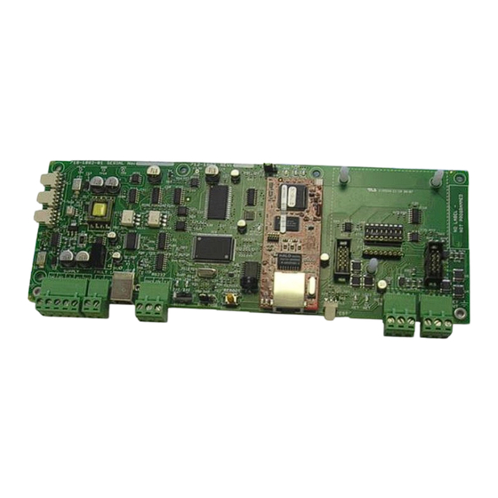
Summary of Contents for Advanced Mxp-554
- Page 1 ipGateway The operation and functions described in this manual are available from Software Version Mx5000-050-04 onwards. www.advancedco.com...
-
Page 2: Specifications
Specifications: Models, Sales Order Parts: ipGateway LAN Interface – Card Only (/FT = Fault Tolerant network) Mxp-554 ipGateway LAN Interface – Boxed (/FT = Fault Tolerant network) Mxp-554-BX Applications / Limitations: Provides remote access to devices on an Ad Net network. -
Page 3: Table Of Contents
Table of Contents Page INTRODUCTION............................. 5 ............................... 5 OUNTING ..............................5 IRING DC P ..........................6 OWER UPPLY ............................6 AULT NPUT ......................... 6 ETWORK ONNECTIONS RS232 S ........................7 ERIAL NTERFACE 10 B -T E ........................7 THERNET ....................... 7 OMMISSIONING THE NTERFACE .......................... - Page 4 RIVATE INTERNAL ACCESS ACROSS AN EXISTING WHERE EXTERNAL EMAIL NOTIFICATIONS ARE ................................24 REQUIRED 6.3.1 Configuration elsewhere on the network ..................24 6.3.1.1 Email Server ............................24 ..24 UBLIC ACCESS ACROSS THE NTERNET WHERE EXTERNAL EMAIL NOTIFICATIONS ARE NOT REQUIRED 6.4.1 Configuration elsewhere on the network ..................
-
Page 5: Introduction
Introduction The ipGateway connects to an existing Ad-Net fire network, providing a gateway to the local fire network from any remote location via the internet. By gathering real time information from the fire network it gives a visual indication of the state of the fire network through a standard web browser. -
Page 6: Dc Power Supply
10Base-T Network Network DC Power Fault RS232 Setup Switch Input Input (SW1) Ethernet Port 1.1 DC Power Supply The MXP554 requires a 24V power supply. Dual terminal screws are provided so that, if required, the DC Power can be routed on to Connect the 24V DC supply feed to the another peripheral unit. -
Page 7: Rs232 Serial Interface
1.4 RS232 Serial Interface The connection to the PC Configuration Tool is via a serial RS232 connector as tabled below. Terminal Function GND (0V) RS232 ground reference RS232 Transmit data to external BMS system RS232 Receive data from BMS system 1.5 10 Base-T Ethernet Port Connect a standard straight through RJ45 Ethernet cable to an existing LAN or router. -
Page 8: Changing The Interface Settings
1.8 Changing the interface settings The above defaults can be changed as NORMAL required after moving switch SW1 over to the “Setup” position (i.e. move to left). SETUP Use any of the following:- Connect a PC to the RS232 connector and run the “Virtual Terminal” display and select “Setup” from the virtual display. -
Page 9: Ip Address
2.1.1 IP Address An IP Address is a unique address which allows a device to be identified on a computer network. IP Addresses essentially come in two forms: Public / Static IP Address Private IP Address A public (or static) IP address allows a device to exist on the internet. Many Internet Service Providers (ISP) offer packages which include static IP addresses as part of a package. - Page 10 Example 1: To access the Web Server, an external user would type the following into the address bar of their browser This will direct data to Port 80 (the default HTTP port) on the router with IP address 212.188.225.200. When this data reaches the router it will be redirected to Port 80 on the device with IP address 10.101.100.21.
-
Page 11: Subnet Mask
2.1.2 Subnet Mask The subnet mask is used to identify sub networks from a given IP address. This allows the possibility to break down a single network into a number of smaller networks. Possible values for Subnet Mask are Subnet Mask Available Networks 255.255.255.0 255.255.255.128... -
Page 12: Administrator Password
2.1.9 Administrator Password When a browser first navigates to the ipGateway, the user will be presented with a logon dialog box requesting a username and password. The ipGateway has two defined users namely, “admin” and “user”. An administrator is given full read/write access to the ipGateway, unless consent is required from the Ad-Net administrator (see section 2.1.11). -
Page 13: Network Setup
3 Network Setup This diagram shows a basic network setup for the ipGateway. Once the ipGateway has been configured with valid network information, i.e. IP Address etc, it can simply be connected onto the current private network. This will allow the ipGateway to be visible from anywhere on the private network. -
Page 14: The Browser
4 The Browser The information obtained by the ipGateway is accessible through a standard web browser. At the time of writing ipGateway is compatible with Internet Explorer 6.0, 7.0, 8.0 and Firefox 2.0, 3.0 For the remainder of this document Internet Explorer 6 will be used in all examples. 4.1 Navigation To use a browser to navigate to an ipGateway, first open the browser and then type the following in the address bar then press “Go”... -
Page 15: Main Form
4.3 Main Form Shortly after confirming the username and password the ipGateway will display the main form in the user’s web browser. 4.3.1 Anatomy of the Main Form The Main Form is broken into five different areas as described below: Status Panel Sub Toolbar Content... -
Page 16: Status Panel
4.3.1.4 Status Panel The Status Panel gives a textual representation of the state of the ad-Net fire network. 4.3.1.5 Control Panel The Control Panel is split into two sections. The first is an LED representation of the state of the Ad-Net fire network, similar to that of a typical fire panel. -
Page 17: Enable / Disable A Device
4.4.1 Enable / Disable a Device A user with full access to the ipGateway (see section 2.1.11) has the ability to enable and disable individual devices using their web browser. Clicking on the “disable” link associated with the device will instruct the ipGateway to disable that device on the Ad-Net fire network. -
Page 18: Events Configuration
4.5 Events Configuration The ipGateway monitors the Ad-Net fire network for a number of defined system events namely fires, faults, disablements, plant alarms, alarms and test alarms. On such an event occurring, the ipGateway can be configured to send a notification email to a number of recipients. -
Page 19: Event Configuration
4.5.2 Event Configuration The ipGateway can be configured to provide email notification of several system events. Click on the “Event Configuration” button the sub-toolbar. Each event is broken into eight weekday and eight weekend shifts (see section 4.5.3 for a description of shifts). -
Page 20: Text
Once the shifts have been defined as required, the information must be sent to the server using the “Send update to Server” button . When the server has received the update, both the “Send update to Server” and the “Synchronise with server” button will be greyed out. If, after defining the shifts, the decision is made to return to the shifts already defined on the server, press the “Synchronise with server”... -
Page 21: Panel Operation
5 Panel Operation On site the building supervisor/user can be assisted with operations such as disabling/enabling a detector from external commands over the TCP/IP network. In order to ensure this only happens with consent from the site an option to allow remote operations is included on the panel and remote terminal enable menu. -
Page 22: Common Configuration Scenarios
6 Common Configuration Scenarios This section outlines some common scenarios and demonstrates which ipGateway configuration settings are required. Each of the scenarios uses the networks described in the following diagram: Site A 192.168.0.100 192.168.0.10 192.168.0.20 Domain: “company.co.uk” ipGateway Email Server 192.168.0.4 74.125.230.148 Router... -
Page 23: Private Internal Access Across An Existing Lan Where No Email Notifications Are Required
6.1 Private internal access across an existing LAN where no email notifications are required Using “Site A” as an example the configuration settings for the ipGateway would be: ipGateway Setting Value IP Address 192.168.0.100 Subnet Mask 255.255.255.0 Admin Password MyAdminPwd User Password MyUserPwd All other configuration settings can be left as default. - Page 24 6.3 Private internal access across an existing LAN where external email notifications are required Using “Site A” as an example the configuration settings for the ipGateway would be: ipGateway Setting Value IP Address 192.168.0.100 Subnet Mask 255.255.255.0 SMTP Server 192.168.0.20 SMTP Username myaccount@company.co.uk SMTP Password...
- Page 25 6.5 Public access across the Internet where external email notifications are required Using “Site A” as an example the configuration settings for the ipGateway would be: ipGateway Setting Value IP Address 192.168.0.100 Subnet Mask 255.255.255.0 Gateway 192.168.0.4 SMTP Server 192.168.0.20 SMTP Username myaccount@company.co.uk SMTP Password...
- Page 26 6.6 Public access across the Internet where an external email server is used This scenario involves sending email via an email server that is not on the private network (LAN). Instead of using a local email server, it is sometimes possible to use an external email server such as those provided by an ISP.
-
Page 27: Troubleshooting
7 Troubleshooting 7.1 Web Page Not Found 7.1.1 Private Network The following are possible reasons for communication with an ipGateway to fail when used on a private network (LAN). 7.1.1.1 IP Address Incorrect Check that the IP Address used to navigate to the ipGateway matches the IP address in the configuration file. 7.1.1.2 Subnet Mask Incorrect Check that the Subnet Mask the ipGateway is using is correct for the network it is connected to. -
Page 28: Incorrect Ip Address For Smtp Server
7.2 Email Not Sent The following are possible reasons that an email message may not be received following an event. 7.2.1 Incorrect IP Address for SMTP Server Check that the ipGateway is configured with the correct IP address for the SMTP server. 7.2.2 User Not Valid on the SMTP Server Check that the “SMTP Username”... - Page 29 ipGateway Request For Information To allow an ipGatway to exist on a LAN, the following information is required from the network administrator: ipGateway Description Setting IP Address of the ipGateway IP Address ___.___.___.___ on the LAN. Subnet Mask for the LAN the Subnet Mask ___.___.___.___ ipGateway will be connected...
- Page 30 This page is intentionally left blank. www.advancedco.com...
- Page 31 USER NOTES www.advancedco.com...
- Page 32 Doc Number: 680-200 Revision: Advanced Electronics Ltd Moorland Way, Cramlington, Northumberland, NE23 1WE UK First Issued: 2013-mm-dd Tel: +44 (0)1670 707 111 Fax: +44 (0)1670 707 222 Email: sales@advancedco.com Web: www.advancedco.com www.advancedco.com...
Need help?
Do you have a question about the Mxp-554 and is the answer not in the manual?
Questions and answers