
Summary of Contents for Ricon Activan
- Page 1 RICON ACTIVAN ILLUSTRATED INDEX NON-OEM VEHICLE EQUIPMENT INCLUDING ELECTRICAL AND PNEUMATIC CIRCUIT DIAGRAMS PLUS DIAGNOSTIC FLOW CHARTS SMA0001.A...
-
Page 2: Table Of Contents
Activan® with Power Door, Power Ramp and Kneeling Suspension Illustrated Index-Equipment Locations and Functions 1 Power Distribution Block 1-1 Remote Control 1-4 In-Floor Ramp Controller 1-6 Single Harness Controller-Windstar 1-14 Single Harness Controller-Caravan 1-19 Leveling Controller 1-24 Height Sensor 1-26... -
Page 3: Power Distribution Block
Power Distribution Block 11593- Located under the steering column next to OEM fuse panel. Accessed by removing OEM fuse cover. Provides power to most Activan® components. It is fed 12 volts from the Circuit Breaker. NOTE ACTUAL FUSE VALUES MAY DIFFER FROM VALUES PRINTED ON BOARD. - Page 4 Power Distribution Block #11593 Name on Board Wire Color Function At Rest In Action Supplied Red 8g Main Power 12V at all times 12V at all times Input Position On Wire Color Function At Rest In Action Connector Supplied Upper terminal Red 10g Power Seat Constant 12V...
- Page 5 Position On Wire Color Function At Rest In Action Connector Supplied Upper pin Black 18g Grounded to Ground Ground Chassis Middle pin Lower pin Blue 18g Parking Zero Ground when Brake Input Parking Brake engaged Name On Board Wire Color Function At Rest In Action...
-
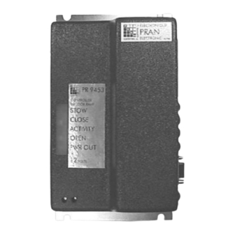
Page 6: In-Floor Ramp Controller
In-Floor Ramp Controller 11584-Installed to operate a Power In-Floor Ramp. The In-Floor Ramp Controller is located under the access panel in the rear cargo area, next to the Single Harness Controller. To access, pull aside flap of carpet, remove (4) Phillips screws, lift panel. In- Floor Ramp Controller is a solid state device used to control the In-Floor Ramp motor. - Page 7 In-Floor Ramp Controller 11584 Amp 10 Pin Connector LED’ s DB9-9 Pin Connector Ramp Adjustment Screws 5/10/99 SMA0001A.PDF...
- Page 8 In-Floor Ramp Controller 11584 Connectors from Single Harness Controller to In-Floor Ramp Controller J11-4 Pin DB9-9 Pin Wire Function At Rest In Action Connector Connector Color Green Blue J10-10 Pin Amp 10 Wire Functions At Rest In Action Connector Color Connector 1-VCC Power to In-Floor...
- Page 9 LED’ s NOTE IF THE SUPPLEMENTAL RELAY BYPASS IS CONNECTED, THE LED’ s WILL ONLY ILLUMINATE WHILE A SWITCH IS DEPRESSED OR THE VEHICLE IS KNEELING. OTHERWISE POWER WILL BE REMOVED FROM THE SINGLE HARNESS CONTROLLER AND IN-FLOOR CONTROLLER. In-Floor Ramp Controller 11584 Label Color...
- Page 10 In-Floor Ramp Controller with White Plastic Adjustment Screws STOW Adjustment DEPLOY Adjustment In-Floor Ramp Controller with White Plastic Adjustment Screws 1. For Deploy direction, the maximum force attained by ramp against a forge-gauge before current limit shuts down, is between 80 lbs. (33 kg.) and 100 lbs. (45 kg.). This will provide for the utmost in safety and reliablity.
- Page 11 travel. The setting should be as high as possible and still accomplish current limit at end-of- travel. A. Locate STOW ADJUSTMENT SCREW. B. Using a screwdriver, turn adjustment screw CCW until it stops (do not force). Ramp is now set for highest current limit, causing motor to stall instead of unit shutting down. C.
- Page 12 In-Floor Ramp Controller with Brass Adjustment Screws DEPLOY STOW 1. Deploy Force Adjustment for Controller with Brass Adjustment Screws: For Deploy direction, the maximum force attained by ramp against a forge-gauge before current limit shuts down, is between 80 lbs. (33 kg.) and 100 lbs. (45 kg.). This will provide for the utmost in safety and reliablity.
- Page 13 2. Stow Force Adjustment for Controller with Brass Adjustment Screws: The current limiting system in stow direction is set so that it is activated only when the ramp has reached its end- of-travel. To perform controller stow force adjustment, follow this procedure: A.
- Page 14 Windstar Single Harness Controller 10502- Located under the access panel in rear of van cargo area. To access, pull aside flap of carpet, remove (4) Phillips screws, lift panel. Major component interface of system. Takes input from switches; directly controls power door and power ramp. NOTE ACTUAL FUSE VALUES MAY DIFFER FROM VALUES PRINTED ON BOARD.
-
Page 15: Single Harness Controller-Caravan
Single Harness Controller 10502 Name on Board Wire Color Function At Rest In Action Interlock Purple Allows system Ground 12V when ignition is to operate off or ignition is on and parking brake Name on Board Wire Color Function At Rest In Action Kneel White... - Page 16 Power Door Harness Name on Board Wire Color Function At Rest In Action White Signal switch Door closed Door open partially: fully: continuity continuity to brown to brown wire- wire-SDA* SDA* Green Signal switch Door open Door open fully (pin n/o allows ramp partially: no switch depressed):...
- Page 17 Power Ramp Harness Name on Board Wire Color Function At Rest In Action FRCS Brown/ Signals when Fully Stowed: Partially Deployed: Orange ramp is Ground Ground Deployed DCLE Brown Signals when Fully stowed: Partially Deployed: ramp is fully Ground none Stowed to allow for door operation...
- Page 18 Caravan Single Harness Controller 11588- Located under the access panel in rear of van cargo area. To access, pull aside flap of carpet, remove (4) Phillips screws, lift panel. Major component interface of system. Takes input from switches; directly controls power door and power ramp. Jumpers JP1 and JP2 (Closed for...
- Page 19 Single Harness Controller 11588 Fuses Function Fuse Type Fuse Rating Power Folding Ramp and ATC blade type automotive 25 Amp Power Door Opener Power Door Latch ATC blade type automotive 15 Amp In-Floor Ramp Controller ATC blade type automotive 20 Amp and In-Floor Ramp Name on Board Wire Color...
- Page 20 Name on Board Wire Color Function At Rest In Action Red 10g 12V input for Ground Is supplied 12V system when switch is in use or leveling controller is active Name on Board Wire Color Function At Rest In Action Black 10g Ground for Ground...
- Page 21 Power Ramp Harness Name on Board Wire Color Function At Rest In Action FRCS Brown/ Signals when Folding Ramp Folding Ramp Orange ramp is Fully open: Partially open: Deployed continuity to continuity to green green wire-RSI* wire-RSI* In-Floor Ramp In-Floor Ramp Fully stowed: Partially Open:...
- Page 22 Name on Board Wire Color Function At Rest In Action White Ramp motor Folding Ramp Folding Ramp deploys; Tied Ground 12V when motor with other deploys ramp (LED RO will light during ROM wire action) In-Floor Ramp In-Floor Ramp 12 volts Pulsed Ground (LED RC will light during action)
- Page 23 LED’ s NOTE IF THE SUPPLEMENTAL RELAY BYPASS IS CONNECTED, THE LED’ s WILL ONLY ILLUMINATE WHILE A SWITCH IS DEPRESSED OR THE VEHICLE IS KNEELING. OTHERWISE POWER WILL BE REMOVED FROM THE SINGLE HARNESS CONTROLLER AND IN-FLOOR CONTROLLER. Single Harness Controller 11588 Label Color...
- Page 24 Remote Control 12782-Located behind the center console, underneath the Dash Controls. Receives RF signals from Remote Controls. Allows for control of Power Door and Power Ramp. Also allows for control of OEM power door locks, if equipped. Receives power from Power Distribution Block.
- Page 25 Remote Control 12782 Small 6 Wire Color Function At Rest In Action Connector Left Side No Pin Black Ground Ground Ground Right Side 12 volt supply from 12 volts positive; no power 12 volts Power Distribution when Interlock is engaged positive Block 7 Pin...
- Page 26 Leveling Controller 260024-Located behind the driver’ s knee bolster, underneath the steering wheel. Controls the functions of the air bag rear suspension. Interprets signals from Leveling Sensor, a pressure switch, and ignition to maintain a level ride height of the vehicle. Controls the inflation and deflation of the rear air bags.
-
Page 27: Height Sensor
Six wire Wire Color Function At Rest In Action Small Molex White Kneeling request Ground 12 volts from Single Harness Controller; initiates kneeling function Orange 25 PSI Pressure Ground when Opens when Switch pressure is pressure inside Air between 0 and 25 Bags is above 25 Brown 40 PSI Pressure... - Page 28 Height Sensor NS5304-Located on top of the rear axle. Connects to the axle and the frame of the vehicle. Maintains a constant ride height, adjusting for variations in cargo weight. Allows for automated raising of the vehicle after the vehicle is kneeled. Water resistant harness connector to Leveling Controller...
-
Page 29: Compressor
Pneumatic Valve Assembly 11825 Caravan; 11974 Windstar-Located underneath the hood, mounted on the radiator core support by the battery. Receives signals from Leveling Sensor, contains the main valve body, Air Dryer, Vent Valve, Manual Air Valve, Pressure Switch, and Left and Right Airbag Valve. - Page 30 Manual Air Valve-Used to manually inflate air bag suspension. Cannot be used to check air pressure in system (due to Airbag valves isolating each air bag from the main manifold). Cannot be used to drain air from system. iCAUTION DO NOT OVERPRESSURIZE THE SYSTEM USING THE MANUAL AIR VALVE. THE SYSTEM IS NOT DESIGNED FOR HIGH PRESSURES.
-
Page 31: Air Valve Assembly
Compressor Assembly 11830 Caravan; 11975 Windstar-Located inside the wheel well on the driver’ s side. It is mounted on a steel bracket behind the plastic wheel well guard. Part of the assembly is the harness that goes from the Leveling Controller to the Air Valve Assembly. The harness contains the diode pack which controls the activation of the Left and Right Air Valves. - Page 32 From Leveling Controller (Closest to Compressor) Wire Color Function At Rest In Action Yellow 14g Send power to Compressor to Continuity to 12 Volts positive operate and to Diode pack which ground opens Right and Left Air Bag Valves Brown Opens The Vent Valve and Continuity to 12 Volts positive...
-
Page 33: Circuit Diagrams 2
Circuit Diagrams 2 Electrical Diagram for Single Harness Controller with Folding Ramp 2-2 Electrical Diagram for Single Harness Controller with In-Floor Ramp 2-4 Electrical Diagram for Leveling System 2-6 Pneumatic Diagram for Leveling System 2-7 5/10/99 SMA0001A.PDF... -
Page 34: Electrical Diagram For Single Harness Controller With Folding Ramp
Electrical Diagram for Single Harness Controller with Folding Ramp (part 1) 5/10/99 SMA0001A.PDF... - Page 35 Electrical Diagram for Single Harness Controller with Folding Ramp (part 2) 5/10/99 SMA0001A.PDF...
- Page 36 Electrical Diagram for Single Harness Controller with In-Floor Ramp (Part 1) 5/10/99 SMA0001A.PDF...
- Page 37 Electrical Diagram for Single Harness Controller with In-Floor Ramp (part 2) 5/10/99 SMA0001A.PDF...
- Page 38 5/10/99...
- Page 39 Pneumatic Schematic for the Leveling System 5/10/99 SMA0001A.PDF...
-
Page 40: Door Position
Position Reference - Functions Displayed with Key Points Door Positions This is the vehicle with the door fully closed. This is the vehicle with the side door partially open. 5/10/99 SMA0001A.PDF... - Page 41 Door Positions (cont'd) This is the vehicle with the door fully open. It has now engaged the “ Door Fully Open ” switch. When this switch is depressed, the Single Harness Controller will begin to deploy the ramp. Door Fully Open switch When the sliding door is fully open, it will depress this switch.
- Page 42 Ramp Positions Folding Ramp This is the Folding Ramp in the fully Stowed position. In this position it has engaged the “ Ramp Fully Stowed” switch. This will allow the door to close under the system’ s operation. This is the Folding Ramp in the fully Deployed position. 5/10/99 SMA0001A.PDF...
- Page 43 Ramp Positions In-Floor Ramp This is the In-Floor Ramp in the fully Stowed position. In this position it has engaged the “ Ramp Fully Stowed” switch. This will allow the door to close under the system’ s operation. This is the In-Floor Ramp while partially Deployed This is the In-Floor Ramp fully Deployed...
- Page 44 Ramp Positions In-floor Ramp-Ramp Stowed Sensor This is a close up of the Stowed Sensor for the In-Floor Ramp. The sensor detects the rear portion of the ramp (driver’ s side of vehicle). It sends a ground signal when it detects that the ramp is fully stowed. Stowed Sensor is mounted here This is the Access Panel underneath the vehicle.
Need help?
Do you have a question about the Activan and is the answer not in the manual?
Questions and answers