Table of Contents
Advertisement
Quick Links
Advertisement
Table of Contents
Troubleshooting

Related Manuals for Leisure Travel Vans Serenity


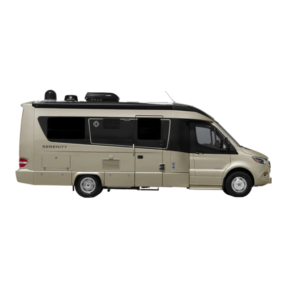
Summary of Contents for Leisure Travel Vans Serenity
- Page 1 Owner’s Manual...
-
Page 2: Table Of Contents
Options and Equipment Driver/Passenger Seat Controls Vehicle Certification Labels Traveling Driving Characteristics Reference Number Codes Certification Label Samples Controls Serenity Floor Plans General Handling Service Assistance High Wind Handling Reporting Safety Defects Mountain Driving Coach Specifications Driving Safety Tips Travel Tips... - Page 3 TABLE OF CONTENTS SERENITY MOTORHOME Door Locks Entertainment Systems Locking and Unlocking Procedures Operating the Smart TV Keys Smart TV Operation Door Strut DVD Operation Entry Door Step TV Utility Panel Entry Step Electrical Diagram External Cable TV Connection Step Override Switch...
- Page 4 SERENITY MOTORHOME TABLE OF CONTENTS LIQUID PROPANE GAS SYSTEM Inverter LP Gas Control Valve Inverter Remote Control Panel Surge Guard (Optional) Safe Use of LP Gas Accidental 240 volt Protection Precautions for the Safe Use of LP Gas How LP Gas Works...
- Page 5 TABLE OF CONTENTS SERENITY MOTORHOME Draining the Water System Adding Plumbing Anti-Freeze Blowing Out the Air Lines De-Winterizing the Water Systems Maintenance and Servicing LP Gas Tank Valve Stabilizers Entry Door Step NEW VEHICLE LIMITED WARRANTY...
-
Page 6: Introduction
For clarification or further details on any of the enclosed information, please contact: Your motorhome has been designed and manufactured to enhance your travel and camping experience and Your Leisure Travel Vans Dealer or Triple E RV Customer to provide you with safe, efficient and trouble-free Service at: operation. -
Page 7: Motorhome Information Kit
OPTIONS AND EQUIPMENT GROSS AXLE WEIGHT RATING (GAWR) Leisure Travel Vans are available in various sizes The value specified as the load carrying capacity of and floor plan configurations and with differing a single axle system, as measured at the tire-ground optional equipment. -
Page 8: Certification Label Samples
SERENITY MOTORHOME INTRODUCTION COLD TIRE INFLATION PRESSURE Inflation pressures recommended (while cold) for the tires originally installed on your motorhome. These tire pressure levels must be maintained to ensure proper handling, safety and fuel economy. LOCATED ON DRIVER-SIDE DOOR FRAME (CANADA MODELS) -
Page 9: Serenity Floor Plans
INTRODUCTION SERENITY MOTORHOME SERENITY FLOOR PLANS S24CB PASSENGER SIDE VIEW Light Entrance Step Furnace Exhaust Refrigerator Vents BBQ Hook-Up Awning External Receptacles Storage Compartment S24CB DRIVER SIDE VIEW Inverter and Storage Compartment Diesel Fill Shore Power Connection Battery Compartment Generator Compartment... - Page 10 SERENITY MOTORHOME INTRODUCTION S24CB TOP SIDE VIEW Solar Panel Radio Antenna Roof Vent Roof Vent TV/Wifi Antenna Skylight Stack Vent Air Conditioner Satellite S24CB REAR VIEW Rear View Camera 7-Pin connector High Mount Brake Light Awning Towing Hitch Storage Compartment...
- Page 11 INTRODUCTION SERENITY MOTORHOME S24CB SOFA FLOOR PLAN S24CB DOUBLE BED FLOOR PLAN...
-
Page 12: Service Assistance
SERENITY MOTORHOME INTRODUCTION SERVICE ASSISTANCE REPORTING SAFETY DEFECTS Your dealer will assist you with any additional information If you suspect your motorhome has a safety defect that you need and will answer any questions you have could cause injury or death, immediately contact Triple about the operation of your motorhome. -
Page 13: Coach Specifications
INTRODUCTION SERENITY MOTORHOME COACH SPECIFICATIONS Chassis 3500 Sprinter Engine - 3.0L V6 Blue TEC Diesel 188hp / 325 lb-ft Torque Transmission - 5 Speed Automatic S24CB Turning Circle - 54.5' Axel Ratio - 3.92:1 Tires - LT215/85R16 GVWR - lbs (kg) -
Page 14: Safety
SERENITY MOTORHOME SAFETY SAFETY or sub-assemblies must be familiar with this manual and the manuals in the Motorhome Information Kit. Every Safety, comfort and ease of operation are key operator and occupant is responsible for following all considerations during the design and manufacture of safety items covered in this and other manuals. -
Page 15: Alarms
SAFETY SERENITY MOTORHOME 9. Test the CO/LP gas alarm before each trip by ALARMS depressing the test button . Test the CO/LP alarm All models are equipped with a combination LP gas, after removing the motorhome from storage, before carbon monoxide, and smoke alarm as standard safety each trip and weekly thereafter. -
Page 16: Fuel And Propane Safety
SERENITY MOTORHOME SAFETY ᘐ WARNING RV. This alarm will cease and return to normal operation after the RV is properly ventilated. Test this alarms operation after each storage PROPANE GAS ALARM period, before each trip and at least once per week during use. -
Page 17: Smoke Alarm
SAFETY SERENITY MOTORHOME ᘐ NOTICE SMOKE ALARM Smoke alarms are not perfect and do not respond The smoke alarm sounds whenever there is an unsafe amount of smoke in the motorhome. Always open the in all situations. The best safeguard is fire prevention. -
Page 18: Emergency Escape
SERENITY MOTORHOME SAFETY FIRE EXTINGUISHER EMERGENCY ESCAPE EGRESS WINDOWS The fire extinguisher is located at the motorhome entrance. In case of fi re, use the following PASS method Use the side entry doors or rear emergency egress to extinguish the fl ames: window exit as emergency escape routes. - Page 19 SAFETY SERENITY MOTORHOME ᘐ WARNING Use of the motorhome is not recommended without a working fi re extinguisher installed. FUNCTION Fire extinguishers are designed to put out a fi re in its initial stages. Once you cannot get within 10 feet (3 m) of the fi...
-
Page 20: Motorhome Operation
SERENITY MOTORHOME MOTORHOME OPERATION MOTORHOME OPERATION that can be added to the motorhome without exceeding the GVWR. Refer to the Certification Labels Samples section on page 7 for visual appearance and relevant locations in the motorhome MOTORHOME PREPARATION Before beginning an extended trip, ensure you are The Gross Combination Weight Rating (GCWR) is the thoroughly familiar with your motorhome’s condition,... -
Page 21: Towing
MOTORHOME OPERATION SERENITY MOTORHOME TOWING AUXILIARY VEHICLE TOWING Towing a trailer can affect the handling, durability, If you are planning to tow another vehicle or a trailer performance and fuel economy of your motorhome. The with your motorhome, contact your local department factory-installed class III towing hitch is rated as follows: of transportation for towing information. -
Page 22: Pre-Trip Inspection
SERENITY MOTORHOME MOTORHOME OPERATION ᘐ DANGER PRE-TRIP INSPECTION 1. Ensure the motorhome and all of its components, Turn off all appliances while refueling any devices, systems and subsystems are serviced and motorhome or LP gas tanks. Do NOT smoke while refueling. -
Page 23: Final Checks
MOTORHOME OPERATION SERENITY MOTORHOME ᘐ WARNING FINAL CHECKS 1. Secure all objects in the motorhome. Tie, latch or All occupants must be in seats equipped with lap lock all loose objects as appropriate. or shoulder harness seatbelts with the seatbelt fastened when the motorhome is in motion. - Page 24 SERENITY MOTORHOME MOTORHOME OPERATION LAP BELTS 2. In accordance with applicable law, your motorhome The dinette is equipped with lap belts . Never allow is not equipped with any anchor or tether system occupants to travel in a seat that is not equipped with on any of its forward facing seats.
-
Page 25: Driver/Passenger Seat Controls
MOTORHOME OPERATION SERENITY MOTORHOME 3. Pull the swivel lock lever (located behind the DRIVER/PASSENGER SEAT seat) to the left, and swivel the seat slowly toward the center line of the motorhome to prevent damage CONTROLS to the seat, door panel and post. -
Page 26: Traveling
SERENITY MOTORHOME MOTORHOME OPERATION BACK REST ADJUSTMENT The motorhome power-to-weight ratio is lower than that Turn the back rest adjustment knob clockwise or of the average automobile. It is essential to compensate counterclockwise to adjust the angle of the seat back. -
Page 27: Driving Safety Tips
MOTORHOME OPERATION SERENITY MOTORHOME ᘐ CAUTION DRIVING SAFETY TIPS Extended brake applications can cause excessive 1. When backing the motorhome, have a person stand wear, overheating and under extreme conditions, to the rear on the driver’s side to guide you. -
Page 28: Severe Weather Information
SERENITY MOTORHOME MOTORHOME OPERATION you are crowding the center line or the outside SEVERE WEATHER INFORMATION edge of the highway. Remember, your motorhome requires a much different driving style than your As a motorhome traveler, you may want to explore new family car. -
Page 29: Emergencies While Driving
MOTORHOME OPERATION SERENITY MOTORHOME 8. Use a jacking board for stability on loose or soft EMERGENCIES WHILE DRIVING ground. Your motorhome is designed with features that allow the 9. Raise the motorhome with the jack according to driver and occupants to resolve some emergencies or the instructions in the chassis manual. -
Page 30: Parking
SERENITY MOTORHOME MOTORHOME OPERATION ᘐ WARNING PARKING BATTERY BOOST WARNING: Consult the chassis PARKING manual in the Motorhome Information Kit for proper jump starting/boosting procedures. You can stop and park your motorhome much like an automobile; however, always remember that the unit is... -
Page 31: Extended Occupancy
MOTORHOME OPERATION SERENITY MOTORHOME BACK-UP MONITORING SYSTEM EXTENDED OCCUPANCY Your motorhome is equipped with a rear camera monitoring system. The rear camera view will Your motorhome is designed for recreational and automatically display on the in-dash entertainment short-term occupancy. In case of extended occupancy,... -
Page 32: Refueling The Vehicle Chassis
SERENITY MOTORHOME MOTORHOME OPERATION Exercise care and caution when parking and REFUELING THE VEHICLE CHASSIS leveling your motorhome. Make sure all pets and people, especially children, are clear of the ᘐ WARNING motorhome until leveling is complete and the motorhome is stable. -
Page 33: Removing The Fuel Cap
MOTORHOME OPERATION SERENITY MOTORHOME DOOR LOCKS REMOVING THE FUEL CAP The fuel tank filler cap is located behind a flap Separate keys are required for the ignition switch adjacent to the driver’s door. Slowly remove the fuel cap installed in the chassis and motorhome door locks. You to release any built up pressure. -
Page 34: Door Strut
Do NOT keep them in your motorhome. Key codes for the chassis can be obtained only through your local authorized Mercedes Sprinter dealer. Each Serenity coach has 3 keys provided: Mercedes Sprinter chassis key , door handle lock... -
Page 35: Entry Door Step
MOTORHOME OPERATION SERENITY MOTORHOME ᘐ NOTICE ENTRY DOOR STEP The entry door step automatically retracts The entry system is equipped with a magnetic interlock system that activates the lowering and raising of the and the step light switches off when you close the coach entrance door and turn vehicle ignition Entry Door Step when the magnetic fi... -
Page 36: Entry Step Electrical Diagram
SERENITY MOTORHOME MOTORHOME OPERATION ENTRY STEP ELECTRICAL DIAGRAM STEP OVERRIDE SWITCH Depress the top of the step override switch , located inside the coach entrance, to prevent the steps from retracting when the coach door is closed. NOTE: The vehicle ignition switch must be in the “OFF”... -
Page 37: Lighting
MOTORHOME OPERATION SERENITY MOTORHOME ᘐ NOTICE LIGHTING Turn the battery disconnect switch on to operate CAB ENTRY LIGHT all internal 12 volt DC lighting. Refer to the “Electrical System Operation” section in this A light is located above each cab door and comes on when the door is opened. -
Page 38: Retracting The Awning
SERENITY MOTORHOME MOTORHOME OPERATION is set to ON. The system works by sensing movement at the end of the awning, and will retract if a certain movement threshold is surpassed. This includes, but is not limited to: wind gusts, heavy rain, excessive rocking of the motorhome, etc. - Page 39 MOTORHOME OPERATION SERENITY MOTORHOME...
-
Page 40: Appliance And Equipment Operation
SERENITY MOTORHOME APPLIANCE AND EQUIPMENT OPERATION APPLIANCE AND Press and hold the power button to turn the refrigerator on and off. After the refrigerator has been EQUIPMENT OPERATION turned on, press one of buttons to select the desired operating mode. The display panel will... -
Page 41: Refrigerator Operating Tips
APPLIANCE AND EQUIPMENT OPERATION SERENITY MOTORHOME STOVE TOP REFRIGERATOR OPERATING TIPS 1. Ensure the refrigerator is cold before placing items The stove top operates on LP Gas. It must be lit manually in it. using the integrated igniter. Ensure the LP gas valve 2. -
Page 42: Microwave/Convection Oven Operating Tips
SERENITY MOTORHOME APPLIANCE AND EQUIPMENT OPERATION cause damage. MICROWAVE/CONVECTION OVEN 5. Turn on the roof vent and open a window to ensure proper ventilation when operating the stove top. OPERATING THE MICROWAVE/ 6. Do not remove the warning label on the stove top lid. -
Page 43: Exterior Bbq Connection
APPLIANCE AND EQUIPMENT OPERATION SERENITY MOTORHOME EXTERIOR BBQ CONNECTION LP GAS FURNACE Your motorhome is equipped with an exterior supply OPERATING THE LP GAS FURNACE source to furnish LP Gas to your own barbeque (BBQ). The connection point is located at the rear on the The LP Gas furnace is controlled by the single-zone passenger side. -
Page 44: Dometic Capacitive Touch Thermostat
SERENITY MOTORHOME APPLIANCE AND EQUIPMENT OPERATION 2. Do not attempt to manually light the furnace. The ROOF AIR CONDITIONER WITH HEAT furnace does not have a pilot light. It is ignited by a direct spark ignition system. PUMP NOTE: Simultaneously hold the thermostat plus (+) -
Page 45: Maintaining The Roof Air Conditioner/Heat Pump
APPLIANCE AND EQUIPMENT OPERATION SERENITY MOTORHOME COACH POWER ROOF VENT MAINTAINING THE ROOF AIR CONDITIONER/HEAT PUMP The coach power roof vent is used to provide controlled Clean or change the air conditioner fi lter at least every air fl ow throughout the coach cabin. Use the vent fan two weeks when the air conditioner is in operation. -
Page 46: Cleaning Instructions
SERENITY MOTORHOME APPLIANCE AND EQUIPMENT OPERATION VENT HOOD HEIGHT CONTROL BATHROOM ROOF VENT The rotary knob controls the height position of the vent hood. Turn the knob clockwise to pull the hood The bathroom roof vent provides air fl ow and venting down and close it. -
Page 47: Side Window Vents
APPLIANCE AND EQUIPMENT OPERATION SERENITY MOTORHOME SIDE WINDOW VENTS MANUAL ROOF VENT Lift the handle and push outward till until it snaps Use the manually operated roof vent in conjunction into position to open the window vent and to close the with the power roof vent to provide adequate air fl... -
Page 48: Closing The Roof Vent
SERENITY MOTORHOME APPLIANCE AND EQUIPMENT OPERATION ENTERTAINMENT SYSTEMS CLOSING THE ROOF VENT 1. Lift the handle to release it from the seat OPERATING THE SMART TV 2. Pull down the roof vent down using the handle 3. Ensure latch securely locks the handle... -
Page 49: Smart Tv Operation
APPLIANCE AND EQUIPMENT OPERATION SERENITY MOTORHOME ZONES VOLUME CONTROL SMART TV OPERATION Refer to the TV manual in the Motorhome Information Kit for detailed operating instructions. ᘐ WARNING AUX 1 HDMI Do NOT watch TV while driving. Do NOT take your eyes off the road for extended periods of time or a crash causing injury or death could result. -
Page 50: Tv Utility Panel
SERENITY MOTORHOME APPLIANCE AND EQUIPMENT OPERATION TV UTILITY PANEL EXTERNAL CABLE TV CONNECTION The TV utility panel is equipped with a TV Your motorhome is equipped with an external cable TV antenna booster/WiFi power switch. The TV antenna hookup connector located in the rear utility center. -
Page 51: Entertainment System Schematics
APPLIANCE AND EQUIPMENT OPERATION SERENITY MOTORHOME ENTERTAINMENT SYSTEM SCHEMATICS SERENITY ENTERTAINMENT SYSTEM SCHEMATIC... -
Page 52: Satellite Pre-Wire Schematic
SERENITY MOTORHOME APPLIANCE AND EQUIPMENT OPERATION SATELLITE PRE-WIRE SCHEMATIC Your motorhome is pre-wired for satellite dish installation (location varies according to floor plan). -
Page 53: Forward Bed
APPLIANCE AND EQUIPMENT OPERATION SERENITY MOTORHOME FORWARD BED SINGLE BED The forward coach seating can be converted into a 1. Remove the cushions from the forward sofa and double or single bed by following the procedures below. chair DOUBLE BED 1. -
Page 54: Electric Rear Sofa
SERENITY MOTORHOME APPLIANCE AND EQUIPMENT OPERATION ELECTRIC REAR SOFA MANUAL OPERATION ᘐ WARNING If the electric fold out function fails to operate, the sofa can be converted to a bed manually by following the The electric sofa bed should only be operated by procedure below. -
Page 55: Removable Table
APPLIANCE AND EQUIPMENT OPERATION SERENITY MOTORHOME 4. Place post on bottom of table in to the opening REMOVABLE TABLE at the top of the support Depending on the selected options, there are either 1 or 2 brackets installed to support the table. -
Page 56: Electrical System Operation
SERENITY MOTORHOME ELECTRICAL SYSTEM OPERATION ELECTRICAL SYSTEM SHORE POWER OPERATION To operate using shore power, connect the 120 volt AC power supply cable (stored in the driver’s side rear exterior storage compartment) to the external receptacle located on the driver’s side of the motorhome. - Page 57 ELECTRICAL SYSTEM OPERATION SERENITY MOTORHOME SERENITY 30 AMP 120V WIRING SCHEMATIC SERENITY 12V WIRING SCHEMATIC...
-
Page 58: System Monitor
SERENITY MOTORHOME ELECTRICAL SYSTEM OPERATION WATER HEATER SWITCH SYSTEM MONITOR This switch controls the power to the water heater. Turn The system monitor panel, located in the wardrobe with the switch counterclockwise from the “OFF” position the two doors, monitors the following systems: for water heater function or clockwise from the “OFF”... -
Page 59: Electrical System Components
ELECTRICAL SYSTEM OPERATION SERENITY MOTORHOME ELECTRICAL SYSTEM COMPONENTS The following major electrical system components are mounted in the dinette seat behind the driver’s seat. • Step 20 amp auto reset breaker • Stabilizer jacks 40 amp auto reset breaker • Jack module •... -
Page 60: 12 Volt Dc Coach Fuses
SERENITY MOTORHOME ELECTRICAL SYSTEM OPERATION NOTE: There is a single 30 amp main circuit breaker 12 VOLT DC CHASSIS FUSES which protects the entire AC electrical system. Check the main breaker if the entire electrical system will not Refer to the chassis operator’s manual for chassis fuse function on shore power or generator (if equipped). -
Page 61: Auxiliary Lp Gas Generator (Optional)
ELECTRICAL SYSTEM OPERATION SERENITY MOTORHOME OPERATING THE AUXILIARY LP GAS GENERATOR Turn on the LP Gas valve by depressing the top of the LP Gas shut off switch located in the utility center in the driver’s side exterior compartment. NOTE: GFCI receptacles may not appear as shown in this manual. -
Page 62: Starting The Auxiliary Lp Gas Generator
One is located on the generator (location a minimum of two hours a month. may vary based on fl oor plan; check “Serenity Floor Plans” page 8). The second button is located in the ᘐ NOTICE electrical utility panel located in the two-door wardrobe. -
Page 63: Starting The Auxiliary Diesel Generator
ELECTRICAL SYSTEM OPERATION SERENITY MOTORHOME STOPPING THE AUXILIARY DIESEL GENERATOR Prior to stopping the generator, turn off all large appliances and let the generator run for two minutes to cool down. To stop the generator, depress the red “Gen OFF”... -
Page 64: Generator Safety
SERENITY MOTORHOME ELECTRICAL SYSTEM OPERATION ᘐ NOTICE obstructions such as vegetation, snow, buildings etc., which could defl ect gas fumes under or into The “Gen OFF” button does not also function as the motorhome. a start switch. The diesel generator can only be... -
Page 65: 12 Volt Dc System
ELECTRICAL SYSTEM OPERATION SERENITY MOTORHOME 12 VOLT DC SYSTEM The 12 volt DC power system in your motorhome consists of the following two distinct, but interconnected, battery systems CHASSIS BATTERY The chassis battery operates the vehicle starter, vehicle accessories and all vehicle controls on the... -
Page 66: Coach Battery Condition Meter
SERENITY MOTORHOME ELECTRICAL SYSTEM OPERATION ᘐ NOTICE COACH BATTERY CONDITION METER A surge protection fuse is installed inside the For voltage readings, refer to Magnum Inverter Remote coach battery storage compartment . If the Control Status display coach batteries fail to operate, inspect this fuse and replace if necessary. -
Page 67: Long-Term Storage
ELECTRICAL SYSTEM OPERATION SERENITY MOTORHOME ᘐ NOTICE LONG-TERM STORAGE Do NOT allow any baking soda solution to get into Turn off the coach battery disconnect during extended periods of storage. Hook up a battery charger at least the battery. This can neutralize the battery acid. -
Page 68: Inverter
SERENITY MOTORHOME ELECTRICAL SYSTEM OPERATION ᘐ CAUTION the manufacturer. The Magnum ME-MR controls the invert and charge features of the inverter. Remove rings, metal watchbands and other ᘐ NOTICE metal jewelry before working around a battery. Use caution when using metal tools. If the tool... -
Page 69: Inverter Remote Control Panel
When shore power is connected it passes through the EMS-LCHW30 surge protection device to protect the wiring in the Serenity. • Do not exceed the rating on the EMS for any reason. These devices are designed to be reduced down to 120V/15A and maintain full protection. -
Page 70: Accidental 240 Volt Protection
SERENITY MOTORHOME ELECTRICAL SYSTEM OPERATION TROUBLESHOOTING GUIDE Error Code Chart In order to help troubleshoot the problem(s) you are experiencing and render the best possible solution, Normal Operating Condition. it is necessary you be at your motorhome when you Reverse Polarity (hot and neutral wires reversed). -
Page 71: Lighting Maintenance
ELECTRICAL SYSTEM OPERATION SERENITY MOTORHOME ᘐ NOTICE REAR INDICATOR/REVERSE/BRAKE/ROAD LIGHTS The solar power unit is intended to charge the coach batteries only. It does not generate enough power to run the motorhome’s electrical system. LIGHTING MAINTENANCE The following procedures detail replacement of the coach interior and exterior lights. -
Page 72: Interior Lighting
SERENITY MOTORHOME ELECTRICAL SYSTEM OPERATION INTERIOR LIGHTING CEILING AND OVERHEAD CABINET LIGHTS 6. Remove the appropriate socket 7. Remove defective bulb and replace with new one. 8. Reinstall socket NOTE: This is a sealed LED unit and must be replaced 9. - Page 73 ELECTRICAL SYSTEM OPERATION SERENITY MOTORHOME INTERIOR SHOWER LIGHT EXTERIOR UTILITY CENTER INCANDESCENT LIGHT The exterior utility center light is controlled by the exterior storage and utility center light switch inside the coach. Refer to the “Exterior/Interior Light Switches” section in the “Motorhome Operation” section for instructions.
- Page 74 SERENITY MOTORHOME ELECTRICAL SYSTEM OPERATION The baggage compartment light is controlled by the exterior storage and utility center light switch inside the coach. Refer to the “Exterior/Interior Light Switches” section in the “Motorhome Operation” section for instructions. NOTE: This is a sealed LED unit and must be replaced as complete unit.
- Page 75 ELECTRICAL SYSTEM OPERATION SERENITY MOTORHOME...
-
Page 76: Water And Plumbing System
SERENITY MOTORHOME WATER AND PLUMBING SYSTEM WATER AND PLUMBING CITY WATER SUPPLY SYSTEM The city water source supplies your motorhome’s water system with water at pressure of the external source when the water pump is switched off. WATER SUPPLY CONNECTING THE EXTERNAL WATER SUPPLY Your motorhome is designed with fresh water, grey water 1. -
Page 77: Filling The Fresh Water Tank
WATER AND PLUMBING SYSTEM SERENITY MOTORHOME DISCONNECTING THE CITY WATER SUPPLY 6. Turn on the water pump switch on the system 1. Turn off the city water supply. monitor panel in the two door wardrobe. 2. Relieve the water pressure in the line by opening a 7. -
Page 78: Water Pump Switch
SERENITY MOTORHOME WATER AND PLUMBING SYSTEM DISINFECTING THE WATER TANK WATER PUMP SWITCH To power the water pump one of the three switches Periodically disinfect the fresh water system. Disinfect needs to be turned on. The light above the water... -
Page 79: Water Pump
WATER AND PLUMBING SYSTEM SERENITY MOTORHOME WATER PUMP WATER PUMP INITIAL STARTUP The water pump is designed to supply on-demand 1. Make sure all drain valves are closed. water from the fresh water tank to the various water 2. Turn off the water pump switch and plumbing systems in your motorhome. -
Page 80: Water Pump Electrical Diagram
SERENITY MOTORHOME WATER AND PLUMBING SYSTEM IF WATER PRESSURE DROPS 1. Check faucets and connections for leaks. 2. Make sure faucet aerators and fi lters are clean. 3. Make sure there is water in the tank. 4. Make sure the chassis battery is not discharged. -
Page 81: Draining The Fresh Water System
WATER AND PLUMBING SYSTEM SERENITY MOTORHOME DRAINING THE FRESH WATER WATER FILTER The water filter is located in the rear storage SYSTEM compartment. Replace the water fi lter at least annually To drain the fresh water tank , open the fresh water to ensure water quality. -
Page 82: Waste Systems
SERENITY MOTORHOME WATER AND PLUMBING SYSTEM WASTE SYSTEMS DUMPING HOLDING TANKS 1. Connect the sewer hose to the tank outlet located GREY WATER WASTE HOLDING TANK on the rear driver’s side underbody. The sewer hose The drainage from the kitchen sink and shower pan is is stored on the driver’s side in front of the rear mask. -
Page 83: Macerator
WATER AND PLUMBING SYSTEM SERENITY MOTORHOME water supply hose to the connector located in MACERATOR the exterior utility center. Your motorhome may be equipped with a macerator . The macerator breaks down the solid matter in the black water holding tank. -
Page 84: Waste Water Holding Tank Do's And Don'ts
SERENITY MOTORHOME WATER AND PLUMBING SYSTEM Refer to the macerator manual located in the Motorhome USING ON-SITE SEWER HOOK-UPS Information Kit for further information. When staying at a campsite where sewer hook-up is available, the sewer hose may be attached and left in WASTE WATER HOLDING TANK DO’S AND... -
Page 85: Water Heater
WATER AND PLUMBING SYSTEM SERENITY MOTORHOME WATER HEATER WATER HEATER OPERATION The water heater is accessible from outside the coach. The water heater is designed to operate on LP gas only and is a tankless pressure operating system which provides hot water on demand. -
Page 86: Switching On The Appliance
SERENITY MOTORHOME WATER AND PLUMBING SYSTEM SWITCHING ON THE APPLIANCE LED ROTARY SWITCH 1. Open the access door. With the rotary switch you can choose between the 2. To switch on the appliance, switch the POWER following operating modes: switch to one of the two “ON” positions. Both ON positions on the POWER switch have the same function. -
Page 87: Water Fixtures
WATER AND PLUMBING SYSTEM SERENITY MOTORHOME ᘐ NOTICE Press the lever to activate the spray nozzle. For safety reasons, after 30 seconds the Refer to toilet operating instructions in the Motorhome decalcifi cation process cannot be stopped until Information Kit for further details. -
Page 88: Showers
SERENITY MOTORHOME WATER AND PLUMBING SYSTEM SHOWERS EXTERIOR SHOWER HOT WATER Your motorhome is equipped with an exterior shower This standard water tap controls the fl ow of hot water to unit located in the exterior utility center. the shower head. Turn clockwise to turn off the water, and counterclockwise to turn on the water. - Page 89 WATER AND PLUMBING SYSTEM SERENITY MOTORHOME...
-
Page 90: Liquid Propane Gas System
SERENITY MOTORHOME LIQUID PROPANE GAS SYSTEM LIQUID PROPANE GAS SAFE USE OF LP GAS SYSTEM The LP Gas system is designed and built to adhere to federal government and industry regulatory LP (Liquid Petroleum) Gas is a colorless gas compressed requirements. -
Page 91: How Lp Gas Works
LIQUID PROPANE GAS SYSTEM SERENITY MOTORHOME HOW LP GAS WORKS There are two types of LP (liquid petroleum) Gas: propane and butane. Both are compressed into a liquid state for easier transportation and storage. Common names used for LP Gas are tank gas, bottle gas, or simply LP. -
Page 92: After Refilling The Lp Gas Tank
SERENITY MOTORHOME LIQUID PROPANE GAS SYSTEM LP Gas stations are found in all parts of the country. AFTER REFILLING THE LP GAS TANK Check the yellow pages in your telephone book or on-line if you have trouble finding a station. Look under 1. -
Page 93: Lp Gas Tank Regulator
LIQUID PROPANE GAS SYSTEM SERENITY MOTORHOME ᘐ CAUTION LP GAS TANK REGULATOR Do not use an open flame or a heat lamp to thaw The LP Gas tank regulator has a plastic cover to protect it from the weather. Only qualified service personnel are the regulator. -
Page 94: Avoiding Asphyxiation
SERENITY MOTORHOME LIQUID PROPANE GAS SYSTEM exhaust fumes into the motorhome. AVOIDING ASPHYXIATION NOTE: When the motorhome is new, some of the 1. Do not use portable fuel-burning equipment such as wood or charcoal grills, heaters or stoves inside the appliances will burn off paint or residue which has motorhome. - Page 95 LIQUID PROPANE GAS SYSTEM SERENITY MOTORHOME...
-
Page 96: Motorhome Maintenance
SERENITY MOTORHOME MOTORHOME MAINTENANCE MOTORHOME MAINTENANCE This will not only improve the appearance of your motorhome, but will also protect the painted surfaces from oxidation and corrosion making it easier to wash. EXTERIOR CARE AND MAINTENANCE ᘐ NOTICE ROOF These instructions are provided as a general guideline only and may not be complete. -
Page 97: Solar Panels
MOTORHOME MAINTENANCE SERENITY MOTORHOME SOLAR PANELS SPOTS AND STAINS Solar panels should be cleaned monthly using water and Most spots and stains can be removed using clear warm a soft sponge or cloth. If required, a mild non-abrasive water. To prevent a stain from spreading, start from the cleanser can be used for more stubborn residue. -
Page 98: Walls
SERENITY MOTORHOME MOTORHOME MAINTENANCE ᘐ NOTICE WALLS Some units contain acrylic (Plexiglas®) Clean walls using warm water and mild soap. For extensive accumulations of dirt and grime, add a small components. Refer to the acrylic manufacturer’s cleaning instructions. Do NOT clean using quantity of rubbing alcohol to the water. -
Page 99: Microwave/Convection Oven
MOTORHOME MAINTENANCE SERENITY MOTORHOME STORAGE AND WINTERIZATION MICROWAVE/CONVECTION OVEN Keep the door and inside of your microwave/convection Inspect all systems, components and appliances prior oven clean. Do not allow grease, spatter or solid matter to storing your motorhome. to build up. An accumulation of solid matter can absorb microwave energy and increase cooking time. -
Page 100: Cold Temperature Storage
SERENITY MOTORHOME MOTORHOME MAINTENANCE COLD TEMPERATURE STORAGE WATER SYSTEM WINTERIZATION - DRAINING 1. Drain the fresh water tank by opening the fresh water tank drain valve . Refer to the “Water and Plumbing System” section for location details. 6. Attach the blow out plug to the city water hookup in the utility center. -
Page 101: Spring Startup
MOTORHOME MAINTENANCE SERENITY MOTORHOME ᘐ WARNING SPRING STARTUP Do NOT use alcohol-based antifreeze or other After storing the motorhome for an extended period of time, run the water pump to pressurize the water system petroleum products. and check for leaks. Visually inspect the water system for 15 minutes to ensure there are no leaks. -
Page 102: Adding Plumbing Anti-Freeze
SERENITY MOTORHOME MOTORHOME MAINTENANCE fresh water before reinstalling both components on the water pump. 4. Go outside and remove the screen from the city water fill connection, depress the center stem until no more fl uid drains out (you may or may not see any fl... -
Page 103: De-Winterizing The Water Systems
MOTORHOME MAINTENANCE SERENITY MOTORHOME remaining water and reinstall the water filter MAINTENANCE AND SERVICING canister. 6. Drain the black and grey waste holding tanks. LP GAS TANK VALVE 7. Add approximately 1 cup of non-toxic plumbing antifreeze to the kitchen sink, bathroom sink, shower... -
Page 104: Entry Door Step
SERENITY MOTORHOME MOTORHOME MAINTENANCE ᘐ NOTICE Refer to the detailed operating and safety instructions in the Motorhome Information Kit before performing the stabilizer override procedure. Stabilizer force can be adjusted using the stabilizer control module located under the driver’s side dinette. - Page 105 MOTORHOME MAINTENANCE SERENITY MOTORHOME...
-
Page 106: New Vehicle Limited Warranty
SERENITY MOTORHOME NEW VEHICLE LIMITED WARRANTY NEW VEHICLE LIMITED parts shall include only the metal structure of the coach and all metal members welded to it, studs WARRANTY and framing in the walls of the coach, roof rafters and delamination of the fiberglass body parts of the TRIPLE E CANADA LTD. - Page 107 NEW VEHICLE LIMITED WARRANTY SERENITY MOTORHOME every such separate warranty with respect to a failure of hoses, fittings, connections or lines and Component as the sole, exclusive and only warranty failure to operate and maintain the Motorhome as in respect of such Component. Triple E RV provides recommended or required in the Owner’s Manual.
- Page 108 SERENITY MOTORHOME NEW VEHICLE LIMITED WARRANTY beyond those expressed herein. Your warranty 9. Time Limitation for Initiating Claims expressly excludes liability for incidental or Any claim for breach of this Warranty or any consequential damages. applicable implied or statutory warranty must be initiated within one year after the date on which the 7.
- Page 109 NOTES SERENITY MOTORHOME NOTES...
- Page 110 LTV Roadside Assistance 4287 Beltline Road, Box #198 Addison, TX 75001 for EMERGENCY ROADSIDE CALL 1•877•219•3831...
- Page 111 Triple E Recreational Vehicles and Leisure Travel Vans are brands and trademarks of Triple E Canada Ltd. 301 Roblin Blvd., Box 1230 Winkler, MB Canada R6W 4C4 Telephone: 204-325-4361 Fax: 204-325-5241 US Address: P.O. Box 68 Walhalla, ND 58282 www.tripleerv.com • info@tripleerv.com • www.leisurevans.com • general@leisurevans.com Product improvement is a continuing process at Triple E Recreational Vehicles.
Need help?
Do you have a question about the Serenity and is the answer not in the manual?
Questions and answers