
Summary of Contents for EDER MCM Series
- Page 1 ANTON EDER GMBH Weyerstraße 350 A-5733 Bramberg www.eder-heizung.at MULTICONTROL C -_2 ... _9 Supplement to instruction manual MCK MCM Instruction manual Ver.10/2019-en...
-
Page 2: Table Of Contents
Table of contents Table of contents General Mounting Installing the device degassing module multicontrol makeup module multicontrol Hydraulic diagrams Wiring diagrams Commissioning Technical data Spare parts list Appendix ECON NOTE! Figures in this document can vary due to model and configuration of the delivered multicontrol device. -
Page 3: General
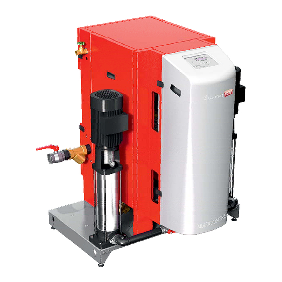
1. General General 1.1. Tender text multicontrol modular for lossless storage of the expansion volume and for pressure maintenance in closed heating, climate and cooling systems. Designed and manufactured acc. to regulations of 12828 and SWKI 93-1. The multicontrol device is a nicely shaped, self-contained unit with a pleasing design. It is designed for a modular combination with external expansion vessels (max. -
Page 4: Mounting
2. Mounting Mounting 2.1. Installing the device The multicontrol device must be installed on a horizontal and solid floor and it must be set up vertically by using the adjustable stands (1). The four holes on side of the socket can be used to transport the device (for example by inserting 2 pipes, max. - Page 5 2. Mounting 2.2. degassing module multicontrol , makeup module multicontrol multicontrol modular series devices factory provided are delivered without degassing module resp. makeup module . The mounting of these modules is done acc. to the assembly instruction which is delivered with the module. connection point MCF connection point MAE figure 2: degassing module MAE...
-
Page 6: Hydraulic Diagrams
3. Hydraulic diagrams Hydraulic diagrams multicontrol modular with degassing: Options: second main vessel -M, additional vessels EGZ-M , expansion modules, degassing module , makeup module , water treatment sensor T2... - Page 7 3. Hydraulic diagrams multicontrol modular without degassing: Options: second main vessel -M, additional vessels EGZ-M , expansion modules, makeup module , water treatment sensor T2...
- Page 8 3. Hydraulic diagrams multicontrol modular without degassing: Options: second main vessel -M, additional vessels EGZ-M , expansion modules, makeup module , water treatment sensor T2, cooling vessel...
-
Page 9: Wiring Diagrams
4. Wiring diagrams Wiring diagrams... - Page 10 4. Wiring diagrams...
- Page 11 4. Wiring diagrams...
- Page 12 4. Wiring diagrams...
- Page 13 4. Wiring diagrams aaaaaaaaaaaaaaaaaaaaaaaaaaaaaaaaaaa aaaaaaaaaaaaaaaaaaaaaaaaaaaaaaaaaaa notes aaaaaaaaaaaaaaaaaaaaaaaaaaaaaaaaaaa aaaaaaaaaaaaaaaaaaaaaaaaaaaaaaaaaaa aaaaaaaaaaaaaaaaaaaaaaaaaaaaaaaaaaa aaaaaaaaaaaaaaaaaaaaaaaaaaaaaaaaaaa aaaaaaaaaaaaaaaaaaaaaaaaaaaaaaaaaaa aaaaaaaaaaaaaaaaaaaaaaaaaaaaaaaaaaa aaaaaaaaaaaaaaaaaaaaaaaaaaaaaaaaaaa aaaaaaaaaaaaaaaaaaaaaaaaaaaaaaaaaaa aaaaaaaaaaaaaaaaaaaaaaaaaaaaaaaaaaa aaaaaaaaaaaaaaaaaaaaaaaaaaaaaaaaaaa aaaaaaaaaaaaaaaaaaaaaaaaaaaaaaaaaaa...
-
Page 14: Commissioning
5. Commissioning Commissioning NOTE! Commissioning by the eder customer service resp. an authorized partner and training of the operating personell is recommended! Commissioning procedure: NOTE! Steps 1-3 must be completed on site in preparation for the commissioning. + min. 5m safety margin step 1 Determine the upper working pressure. - Page 15 5. Commissioning step 6 Switch on power supply and check if the red control lamp beside the key ”0” glows. If not, deactivate the device by pressing the key ”0” and following confirmation by pressing the key ”F1” (red control lamp beside the key ”0” must glow!) step 7 Fill and ventilate the pressure maintenance pump(s) and the piping.
- Page 16 5. Commissioning INFORMATION! Shut off all expansion vessels except the first -M vessel previously to accelerate the filling. - If a makeup module is not installed, you have to fill the vessel (e.g. via the emptying at the connection of the overflow pipe - see figure 5, detail B) until a continuous water jet leaks from the ventilation valve (detail A) at the pressure maintenance pump.
- Page 17 5. Commissioning User level 3 .))) device set-up /))) vessel code .))) acc. to the sticker at the vessel /))) correction value .))) acc. to the sticker at the upper pressure transmitter /))) correction value .))) acc. to the sticker at the lower pressure transmitter /))) makeup /))) not available (default setting) .))) is available...
- Page 18 5. Commissioning .))) digital input /))) not available (default setting) /))) warning: contact open /))) warning: contact closed /))) error: contact open .))) error: contact closed INFORMATION! If device setup was completed successfully (only mandatory inputs necessary) this menu item is removed permanently. The device setup always is available in ”user level 3" g ”settings”.
- Page 19 5. Commissioning step 11 Set the working pressure - Open the shut off devices from/to system return expansion pipe, makeup). If a degassing module is installed, the ball valve at its intake side must be closed. Due to the size of the system the setting of the working pressure can take up a lot of time because the pressure has to extend into the entire connected system to be stable for the setting.
- Page 20 5. Commissioning step 12 If a makeup module is installed, the operating mode must be selected. The operating mode is depending on several criteria such as size of the system, age of the system, possible known leakage and so on. If there are known and regular leakages (e.g.
- Page 21 5. Commissioning aaaaaaaaaaaaaaaaaaaaaaaaaaaaaaaaaaa aaaaaaaaaaaaaaaaaaaaaaaaaaaaaaaaaaa aaaaaaaaaaaaaaaaaaaaaaaaaaaaaaaaaaa notes aaaaaaaaaaaaaaaaaaaaaaaaaaaaaaaaaaa aaaaaaaaaaaaaaaaaaaaaaaaaaaaaaaaaaa aaaaaaaaaaaaaaaaaaaaaaaaaaaaaaaaaaa aaaaaaaaaaaaaaaaaaaaaaaaaaaaaaaaaaa aaaaaaaaaaaaaaaaaaaaaaaaaaaaaaaaaaa aaaaaaaaaaaaaaaaaaaaaaaaaaaaaaaaaaa aaaaaaaaaaaaaaaaaaaaaaaaaaaaaaaaaaa aaaaaaaaaaaaaaaaaaaaaaaaaaaaaaaaaaa aaaaaaaaaaaaaaaaaaaaaaaaaaaaaaaaaaa aaaaaaaaaaaaaaaaaaaaaaaaaaaaaaaaaaa aaaaaaaaaaaaaaaaaaaaaaaaaaaaaaaaaaa aaaaaaaaaaaaaaaaaaaaaaaaaaaaaaaaaaa aaaaaaaaaaaaaaaaaaaaaaaaaaaaaaaaaaa aaaaaaaaaaaaaaaaaaaaaaaaaaaaaaaaaaa aaaaaaaaaaaaaaaaaaaaaaaaaaaaaaaaaaa aaaaaaaaaaaaaaaaaaaaaaaaaaaaaaaaaaa aaaaaaaaaaaaaaaaaaaaaaaaaaaaaaaaaaa aaaaaaaaaaaaaaaaaaaaaaaaaaaaaaaaaaa aaaaaaaaaaaaaaaaaaaaaaaaaaaaaaaaaaa aaaaaaaaaaaaaaaaaaaaaaaaaaaaaaaaaaa aaaaaaaaaaaaaaaaaaaaaaaaaaaaaaaaaaa aaaaaaaaaaaaaaaaaaaaaaaaaaaaaaaaaaa aaaaaaaaaaaaaaaaaaaaaaaaaaaaaaaaaaa aaaaaaaaaaaaaaaaaaaaaaaaaaaaaaaaaaa aaaaaaaaaaaaaaaaaaaaaaaaaaaaaaaaaaa aaaaaaaaaaaaaaaaaaaaaaaaaaaaaaaaaaa aaaaaaaaaaaaaaaaaaaaaaaaaaaaaaaaaaa aaaaaaaaaaaaaaaaaaaaaaaaaaaaaaaaaaa aaaaaaaaaaaaaaaaaaaaaaaaaaaaaaaaaaa aaaaaaaaaaaaaaaaaaaaaaaaaaaaaaaaaaa aaaaaaaaaaaaaaaaaaaaaaaaaaaaaaaaaaa aaaaaaaaaaaaaaaaaaaaaaaaaaaaaaaaaaa aaaaaaaaaaaaaaaaaaaaaaaaaaaaaaaaaaa aaaaaaaaaaaaaaaaaaaaaaaaaaaaaaaaaaa aaaaaaaaaaaaaaaaaaaaaaaaaaaaaaaaaaa aaaaaaaaaaaaaaaaaaaaaaaaaaaaaaaaaaa aaaaaaaaaaaaaaaaaaaaaaaaaaaaaaaaaaa...
-
Page 22: Technical Data
6. Technical data 6 Techni cal data type elko-mat eder multicontrol modular solo art.no. max. upper working pressure nominal pressure device ( max.temperature at plant connect. °C voltage V/Hz 1x 230 3x 400 V 50 Hz max. electrical power fuse protection connections "... - Page 23 6. Technical data MCM-M9-6,6-twin 052768 2,4-6,6 MCM-M9-11,0-twin 052778 6,0-11,0 MCM-M9-6,6 052568 2,4-6,6 MCM-M9-11,0 052578 6,0-11,0 MCM-M8-16,0-twin 052767 8,0-16,0 MCM-M8-16,0 052567 8,0-16,0 MCM-M7-6,6-twin 052766 2,4-6,6 MCM-M7-6,6 052566 2,4-6,6 MCM-M6-6,6-twin 052775 2,4-6,6 MCM-M6-10,0-twin 052765 4,0-10,0 MCM-M6-6,6 052575 2,4-6,6 MCM-M6-10,0 052565 4,0-10,0 MCM-M5-6,2-twin 052764 2,4-6,2 MCM-M5-6,2...
- Page 24 6. Technical data MCM-D9-6,6-twin 052738 2,4-6,6 MCM-D9-11,0-twin 052748 6,0-11,0 MCM-D9-6,6 052538 2,4-6,6 MCM-D9-11,0 052548 6,0-11,0 MCM-D8-16,0-twin 052737 8,0-16,0 MCM-D8-16,0 052537 8,0-16,0 MCM-D7-6,6-twin 052736 2,4-6,6 MCM-D7-6,6 052536 2,4-6,6 MCM-D6-6,6-twin 052745 2,4-6,6 MCM-D6-10,1-twin 052735 6,0-10,1 MCM-D6-6,6 052545 2,4-6,6 MCM-D6-10,1 052535 6,0-10,1 MCM-D5-6,2-twin 052734 2,4-6,2 MCM-D5-6,2...
-
Page 25: Spare Parts List
7. Spare parts list 7. Spare parts list 7.1. Piping... - Page 26 7. Spare parts list Item Description Spare part no. System solo pressure maintenance pump 90357 90359 90360 90361 90362 overflow valve 90603 90604 90121 90119 90121 90115 90119 90539 90119 90606 mud flap 90932 90933 90934 90933 temperature sensor for mc 90911 plant pressure transmitter 90140...
- Page 27 7. Spare parts list 7.2. Makeup module MCF Version A Version B Item Description Spare part no. water meter 1,5 m³/h, type A 90906 water meter 2,5 m³/h, type A 90925 water meter pulse output module 1 liter/puls snap-on, for water meter type A 90907 magnetic valve 90575...
- Page 28 7. Spare parts list 7.3. Load circuit item description spare part no. contactor 90919 circuit breaker 90920 motor protection switch 4 A (2,5-4,0 A) 6,3 A (4,0-6,3 A) 10 A (6,3-10,0 A) 90921 90922 90923 main switch 90924 7.4. Degassing module MAE Item Description Spare part no.
-
Page 29: Appendix
8. Appendix Appendix Hydraulic connection between EG(Z)-M multicontrol modular series devices don‘t have a built-on vessel. The expansion volume must be stored in external series expansion vessels. To enlarge the expansion volume, -M series additional expansion vessels must be used. Generally the connection of the particular devices must be installed on-site according to the appropriate piping diagram in chapter 3. - Page 30 8. Appendix 2. Installation of the suction pipe bends, crossover- Sometimes it is necessary to cross the overflow pipe and the fittings etc. only in overflow pipe suction pipe to connect (Z)-M correctly. Please note that the suction pipe is installed without any differences in level.
- Page 31 Notes aaaaaaaaaaaaaaaaaaaaaaaaaaaaaaaaaaa aaaaaaaaaaaaaaaaaaaaaaaaaaaaaaaaaaa aaaaaaaaaaaaaaaaaaaaaaaaaaaaaaaaaaa notes aaaaaaaaaaaaaaaaaaaaaaaaaaaaaaaaaaa aaaaaaaaaaaaaaaaaaaaaaaaaaaaaaaaaaa aaaaaaaaaaaaaaaaaaaaaaaaaaaaaaaaaaa aaaaaaaaaaaaaaaaaaaaaaaaaaaaaaaaaaa aaaaaaaaaaaaaaaaaaaaaaaaaaaaaaaaaaa aaaaaaaaaaaaaaaaaaaaaaaaaaaaaaaaaaa aaaaaaaaaaaaaaaaaaaaaaaaaaaaaaaaaaa aaaaaaaaaaaaaaaaaaaaaaaaaaaaaaaaaaa aaaaaaaaaaaaaaaaaaaaaaaaaaaaaaaaaaa aaaaaaaaaaaaaaaaaaaaaaaaaaaaaaaaaaa aaaaaaaaaaaaaaaaaaaaaaaaaaaaaaaaaaa aaaaaaaaaaaaaaaaaaaaaaaaaaaaaaaaaaa aaaaaaaaaaaaaaaaaaaaaaaaaaaaaaaaaaa aaaaaaaaaaaaaaaaaaaaaaaaaaaaaaaaaaa aaaaaaaaaaaaaaaaaaaaaaaaaaaaaaaaaaa aaaaaaaaaaaaaaaaaaaaaaaaaaaaaaaaaaa aaaaaaaaaaaaaaaaaaaaaaaaaaaaaaaaaaa aaaaaaaaaaaaaaaaaaaaaaaaaaaaaaaaaaa aaaaaaaaaaaaaaaaaaaaaaaaaaaaaaaaaaa aaaaaaaaaaaaaaaaaaaaaaaaaaaaaaaaaaa aaaaaaaaaaaaaaaaaaaaaaaaaaaaaaaaaaa aaaaaaaaaaaaaaaaaaaaaaaaaaaaaaaaaaa aaaaaaaaaaaaaaaaaaaaaaaaaaaaaaaaaaa aaaaaaaaaaaaaaaaaaaaaaaaaaaaaaaaaaa aaaaaaaaaaaaaaaaaaaaaaaaaaaaaaaaaaa aaaaaaaaaaaaaaaaaaaaaaaaaaaaaaaaaaa aaaaaaaaaaaaaaaaaaaaaaaaaaaaaaaaaaa aaaaaaaaaaaaaaaaaaaaaaaaaaaaaaaaaaa aaaaaaaaaaaaaaaaaaaaaaaaaaaaaaaaaaa aaaaaaaaaaaaaaaaaaaaaaaaaaaaaaaaaaa aaaaaaaaaaaaaaaaaaaaaaaaaaaaaaaaaaa aaaaaaaaaaaaaaaaaaaaaaaaaaaaaaaaaaa aaaaaaaaaaaaaaaaaaaaaaaaaaaaaaaaaaa aaaaaaaaaaaaaaaaaaaaaaaaaaaaaaaaaaa aaaaaaaaaaaaaaaaaaaaaaaaaaaaaaaaaaa aaaaaaaaaaaaaaaaaaaaaaaaaaaaaaaaaaa aaaaaaaaaaaaaaaaaaaaaaaaaaaaaaaaaaa aaaaaaaaaaaaaaaaaaaaaaaaaaaaaaaaaaa...
- Page 32 Anton Eder GmbH main plant headquarters Weyerstraße 350, A 5733 Bramberg Tel. 06566 / 7366 Fax. 06566 / 8127 E-mail: info@eder-heizung.at branch office representation s / ervice center Leisach 52, A 9909 Leisach Tel. 04852 / 64477 Fax. 04852 / 64477-20 E-mail: lienz@eder-heizung.at...
Need help?
Do you have a question about the MCM Series and is the answer not in the manual?
Questions and answers