Table of Contents
Advertisement
Advertisement
Table of Contents

Summary of Contents for Incite Fire FIREscape
- Page 1 Emergency Lighting System INSTALLATION MANUAL...
- Page 2 FIREscape System Installation Manual Title: FIREscape System Installation Manual Issue Issue Date: February 2017 Part No. 2-3-0-1331AS Page 4 of 56...
-
Page 3: Table Of Contents
FIREscape System Installation Manual Contents Introduction ..........................7 Overview ............................8 Standards ............................. 8 Cables and Cable Screen ..................... 8 Installation Environment ......................9 Panel Housing ..........................9 Installation ..........................9 EL-KP Keypad ..........................11 Overview ..........................11 Installation ..........................13 Connection ..........................14 Settings............................15... - Page 4 FIREscape System Installation Manual 12.4.2 24m Exit Sign Technical Specifications ..............32 12.5 NF89-O-AS High Powered Emergency Escape Open Area Down Light ......33 12.5.1 NF89-O-AS Technical Specifications ............... 33 12.5.2 NF89-O-AS Classifications & Mounting Heights ............33 12.6 NF89-C-AS High Powered Emergency Corridor Escape Down Light ........ 34 12.6.1 NF89-C-AS Technical Specifications ................
-
Page 5: Introduction
All luminaires are intelligent and given an address on the system to be easily identified. This address consists of a line number and a device number. The Hochiki FIREscape range includes 16 meter to 24-meter range of emergency exit signs with the ability to be either wall or ceiling mounted, single sided or double sided. -
Page 6: Overview
FIREscape System Installation Manual Overview This guide covers the installation of the FIREscape system featuring the EL-2 Emergency Lighting Control Panel Figure 1 - FIREscape System Standards The system implements device tests, fault monitoring and reporting conformant to Australian standards AS2293. -
Page 7: Installation Environment
FIREscape System Installation Manual Installation Environment The operating environment of the system and its connected components must be considered at the design stage prior to installation Panel Housing Installation The weight of the control panel is approximately 8 kg, including 1 x 7 Ah battery. The weight of the control panel must be considered when for wall mounting. - Page 8 FIREscape System Installation Manual Figure 3 - Fixing Hole Template Insert 4 x 2mm screws into the plugs. Lift the control panel housing to the wall and guide the screws into the screw grooves in the housing. ...
-
Page 9: El-Kp Keypad
FIREscape System Installation Manual NOTE: The aperture at the bottom of the housing is for the transformer cable. The apertures at the top of the housing are for other cables. Figure 4 - Measuring Insulation Resistance The insulation resistance is measured for each conductor, including the shield, against the building earth. The insulation resistance must be >1 MΩ. - Page 10 FIREscape System Installation Manual The keypads are connected in parallel to the serial communication bus. The cabling can be a star (through a central node) or ring (through each device). The units do not have to be addressed sequentially. Figure 11 - EL-KP Keypad Connectivity NOTE: The maximum length of the data bus is 500m.
-
Page 11: Installation
FIREscape System Installation Manual Installation The keypad should be installed at an average shoulder level height of around 1500 (+200)mm.FIREscape System Installation Manual Figure 13 - EL-KP Typical Installation Drill 4 holes for the mounting plugs. The hole depth must be 20–25 mm. For the location of the holes, see Figure 14. -
Page 12: Connection
FIREscape System Installation Manual Set the address, configure any other settings required, and connect the 5-pin connector to the keypad. Attach the keypad to the base plate with 3 mm machine screws. The front cover fixing screw is concealed with the supplied self-adhesive cover sticker. -
Page 13: Settings
FIREscape System Installation Manual Settings Figure 15 - EL-KP Settings The address of the keypad is set with the rotary switch SW1. Connect the 5-pin plug into connector X2. Adjust the display contrast, if necessary, after applying power. -
Page 14: Start
FIREscape System Installation Manual Start When the keypad starts (voltage connected or restart), the display will show this text: * KLG remote panel * c. 2005 Oy Hedpro If the data connection to the control panel is working, the keypad’s address is shown, for example Addr 1, along with the software version and the text “Polling OK”... -
Page 15: Connections
FIREscape System Installation Manual EL-2 Connections Figure 16 - EL-2 Motherboard Connections Control Panel Fuses: Description Fuse Value [A] Points Connector 35 VAC 1, 2 Batteries 12VDC 1 (+), 2(-) Voltage for external devices 1, 3 (+), 2, 4(-) Voltage for external devices... -
Page 16: Relay Outputs
FIREscape System Installation Manual Voltage for device connected 0.3 (automatic fuse) to PRG card Voltage for EL-EXP card 0.3 (automatic fuse) NOTE: The total maximum load for outputs F3+F4 is 0.6 A. Relay Outputs The control panel has 2 relay outputs. These can be configured as normally open (N/O) or normally closed (N/C). -
Page 17: Settings
FIREscape System Installation Manual Settings Figure 17 - EL-2 Motherboard Settings Language Selection The language of the control panel is set with the jumpers 1–3. The following settings are possible: Language English Finnish Swedish Norwegian Test mode 4.8 Factory Reset The control panel can be initialised with factory settings: ... -
Page 18: Rs-232 Connectors
FIREscape System Installation Manual RS-232 Connectors PC Interface, PRG PC SERIAL PORT Figure 18 - PC Interface Cable Connection EL-ISOL (RS-232 Isolator) When connecting the control panel’s RS-232 outputs to devices which are earthed, such as PC/printer, the connection may cause interference due to earth leakage. This is because the negative (-) pin of the RS-232 connector is usually connected to shield ground. -
Page 19: El-Isol Connection
FIREscape System Installation Manual EL-ISOL Connection: Figure 19 - EL-ISOL Connection Additional Port, PRN This port can be used for connecting external RS-232 devices Page 21 of 56... -
Page 20: Addressable Emergency Lighting Lines
FIREscape System Installation Manual 10 Addressable Emergency Lighting Lines 10.1 Principle The system luminaires and interfaces are intelligent units equipped with their own batteries (luminaires) and have addresses. The control panel polls the units at approximately 0.75 s intervals per address. All units in the bus (127 devices max) are polled in <100 s. -
Page 21: Emergency Lighting Line Connection
FIREscape System Installation Manual 10.3 Emergency Lighting Line Connection Figure 5 - Wiring the Lighting Line Cable to an EL-TSB Mounting Base The lighting line cable is taken to each line device. The lighting line cabling can be a star (through a central node) or a ring (through each mounting base). - Page 22 FIREscape System Installation Manual Figure 6 - An example of a spur arrangement Page 24 of 56...
-
Page 23: Wiring To House Lighting Via Pm
FIREscape System Installation Manual 11 Wiring to House Lighting via PM There are many ways from which to wire and monitor house lighting. Figure 7 is a typical example of how to do this. Figure 7 - An example of a typical connection to a single lighting circuit... - Page 24 The + from line A or B shall feed in through terminal 15 of the EL-PM, and out of the terminal 18 From terminal 18 the + shall feed into the FIREscape emergency lighting connector block where it will be accompanied by the –...
-
Page 25: Emergency Luminaires
FIREscape System Installation Manual 12 Emergency Luminaires The majority of the FIREscape light units can be fitted directly to the standard mounting base (EL-TSB). 12.1 EL-DL2-AS Escape Corridor Down Light The EL-DL2-AS corridor down light is an LED based, addressable corridor down light... -
Page 26: El-Dl3-As Open Area Down Light
FIREscape System Installation Manual 12.2 EL-DL3-AS Open Area Down Light The EL-DL3-AS open area down light is an LED based, addressable open area down light featuring one high- powered LED with a specially engineered dual surface free-form optic. The unit’s body contains the electronics and... -
Page 27: 16 M Exit Sign
FIREscape System Installation Manual 12.3 16 m Exit Sign The EL-16-AS is an illuminated exit sign intended to be visible up to a distance of 16 meters. There are various models, each with a different arrow direction (indicating the direction of an exit). -
Page 28: 16 M Exit Sign Lenses
FIREscape System Installation Manual 12.3.1 16 m Exit Sign Lenses 12.3.2 16 m Exit Sign Technical Specifications C0: N/A C90: N/A Classification EL-16-AS Exit Sign Frame EL-16G-L-AS (left arrow) Lens Ordering code EL-16G-R-AS (right arrow) EL-16G-S-AS (straight) EL-16G-AS (Reflective Worm, Back plate and Rivet Assy) 24v –... -
Page 29: 24 M Exit Sign
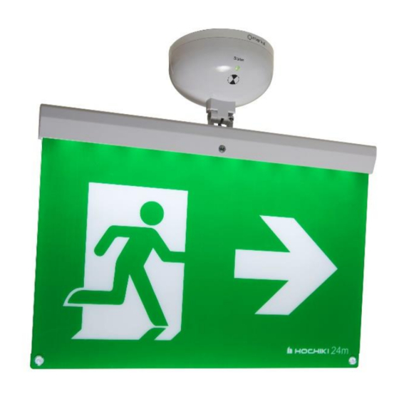
FIREscape System Installation Manual 12.4 24 m Exit Sign The EL-24-AS is an illuminated exit sign intended to be visible up to a distance of 24 meters. There are various models, each with a different arrow direction (indicating the direction of an exit). -
Page 30: Exit Sign Lenses
FIREscape System Installation Manual 12.4.1 24m Exit Sign Lenses 12.4.2 24m Exit Sign Technical Specifications C0: N/A C90: N/A Classification EL-24-AS Exit Sign Frame EL-24G-L-AS (left arrow) Ordering code EL-24G-R-AS (right arrow) EL-24G-AS (straight) EL-24G-AS (Reflective Worm, Back plate and Rivet Assy) 24v –... -
Page 31: Nf89-O-As High Powered Emergency Escape Open Area Down Light
FIREscape System Installation Manual 12.5 NF89-O-AS High Powered Emergency Escape Open Area Down Light The NF89-O-AS open area down light is an LED based, addressable open area down light featuring one high- powered LED with a specially engineered dual surface free-form optic. -
Page 32: Nf89-C-As High Powered Emergency Corridor Escape Down Light
FIREscape System Installation Manual 12.6 NF89-C-AS High Powered Emergency Corridor Escape Down Light The NF89-C-AS Corridor area down light is an LED based, addressable open area down light featuring one high- powered LED with a specially engineered dual surface free-form optic. The unit’s body contains the electronics and the... -
Page 33: El-Sl Step Light
FIREscape System Installation Manual 12.7 EL-SL Step Light The EL-SL is a step level light for use when illuminating staircase steps, changes in floor levels or as a general low- level light. It can also be used to enhance an emergency lighting installation. -
Page 34: El-Io Module
The EL-IO is an input/output unit. The unit has 4 inputs and 2 outputs. A maximum of 16 units can be connected to the FIREscape EL2 control panel. The unit requires an address on the lighting line. The address is set with the unit’s DIL switches. -
Page 35: El-Io Technical Specifications
FIREscape System Installation Manual Figure 10 - EL-IO Wiring Connections 13.1.1 EL-IO Technical Specifications Unit EL-IO 24 – 40V Operating Voltage [VDC] (VAC) Power consumption from line [NU] 2 / 0.1W Page 37 of 56... -
Page 36: El-Exp Expansion Unit
FIREscape System Installation Manual 14 EL-EXP Expansion Unit The EL-EXP connectivity card is used for expanding the serial ports of the EL-2 control panel. The EL- EXP unit provides two additional ports, SER1 and SER2. The EL-EXP is connected to the control panel with the flat cable supplied with the card. The card is connected to the top right corner of the control panel housing with the supplied plastic supports. - Page 37 FIREscape System Installation Manual Figure 20 - EL-EXP Connection Page 39 of 56...
-
Page 38: Tch-B200 Address Programming Device
NOTE: The programmer will turn off by itself approximately 15s after last key press. NOTE: The FIREscape device is set to power save mode after programming. The load of a full battery will last for approximately 2 months. The unit wakes up from the power save mode when line voltage is connected or the battery is removed and reinserted. -
Page 39: Cabling Length
The voltage level of the control panel’s line out is approximately 39 V (high bit) or 34 V (low bit). The FIREscape device’s minimum line voltage is 24 V, which means that 15 V can be dropped through the cable. - Page 40 FIREscape System Installation Manual FireScape line calculator (luminaries, power consumptiom) EL-DL2/3-AS Type Brightness Current ( mA ) Max Line Device Quantity Total mA Total FU EL-DL2/3-AS Factory default ( Route luminaire ) EL-DL2/3-AS 11.6 EL-DL2/3-AS 15.3 EL-DL2/3-AS 18.9 EL-DL2/3-AS 26.3 EL-DL2/3-AS 33.7...
-
Page 41: Illumination Points At Regular Intervals
FIREscape System Installation Manual 16.3 Illumination Points at Regular Intervals KLMA 2x0.8 / 74ohm/km. Devices placed on cable at regular intervals 1750 1750 1500 1270 1270 2 conductor pairs / LOOP / 1.5 1000 1 conductor pair (RADIAL 0.8) 1000... - Page 42 FIREscape System Installation Manual Single-Storey Building Luminaires Branch 1: Luminaires Branch 2: A building with the size 87 pcs EL-16-AS 16m signs @10NU 40 pcs EL-16-AS 16m signs @10NU 50 x 300 m. Power requirement 870NU Power requirement 400NU EL-2 Control Panel, using line A Total power requirement: 1270NU.
- Page 43 FIREscape System Installation Manual Multi-Storey Building Devices per Storey This is a 4-storey 7 pcs EL-16-AS16m signs @10NU building. 48 pcs EL-DL2-AS safety lights @4NU. The surface area of a floor is 40 x 70 m. The distance between the floors is 5 m.
-
Page 44: Other Devices
FIREscape System Installation Manual 16.5 Other Devices The minimum operating voltage of the control panel’s voltage outputs is 10.0 V. When supplying external devices from the EL-2 Control Panel power supply, note the minimum operating voltage of the devices and their maximum power consumption. - Page 45 FIREscape System Installation Manual Example 2 2 pcs EL-KP, maximum current requirement 60mA, The keypads are in a different building, for example, at the minimum operating voltage end of the cable. The current in the cable between the device x, EL-KP 1, and the control panel is a maximum of 60 + 60 mA = 120 mA.
-
Page 46: Devices At Equal Intervals
FIREscape System Installation Manual 16.6 Devices at Equal Intervals Minimum Operating Voltage 6.5 V Figure 27 Page 48 of 56... - Page 47 FIREscape System Installation Manual Minimum Operating Voltage 7.5 V Figure 28 Page 49 of 56...
- Page 48 FIREscape System Installation Manual Minimum Operating Voltage 8.5 V Figure 29 Page 50 of 56...
-
Page 49: Devices At The End Of The Cable
FIREscape System Installation Manual 16.7 Devices at the End of The Cable Minimum Operating Voltage 6.5 V Figure 30 Page 51 of 56... - Page 50 FIREscape System Installation Manual Minimum Operating Voltage 7.5 V Figure 31 Page 52 of 56...
- Page 51 FIREscape System Installation Manual Minimum Operating Voltage 8.5 V Figure 32 Page 53 of 56...
-
Page 52: Technical Specifications
FIREscape System Installation Manual 17 EL-2 Technical Specifications 17.1 Control Panel Control panel model EL-2 Operating environment[°C] 5 - 40 Operating temperature [°C]* 5 - 40 Dimensions (h x w x d) [mm] 347 x 276 x 76 Weight [kg] (includes 7 Ah battery) -
Page 53: System Components
FIREscape System Installation Manual 18 System Components Power save Maximum Power Operating Dimensions current current requirement Unit Desc temperature Voltage [V] consumption consumption on luminaire (L x W x D) [mm] [°C] [mA] [mA] [NU] EL-KP Keypad -10 - 50... - Page 54 FIREscape System Installation Manual Type Luminous Intensity NU Power from Power from battery battery * Factory setting for normal intensity Page 56 of 56...
-
Page 55: Troubleshooting
FIREscape System Installation Manual 19 Troubleshooting 19.1 RS-485 Data Connection Serial Port communications are indicated via LEDs; red (data receive) and green (data send). When the red LED is flashing, the unit is receiving data. This does not mean that the unit understands the data. -
Page 56: Double Address Detection
FIREscape System Installation Manual after approximately 5 s. After the blink, the line has been tested for that address. Remove the safety light and move to the next base and repeat the above process for each luminaire base. 19.3.3 Double Address Detection If the EL-KP key pad reports a double address, it means that more than one device is using the same address.
Need help?
Do you have a question about the FIREscape and is the answer not in the manual?
Questions and answers