
Summary of Contents for DSE DSEGenset DSE8004
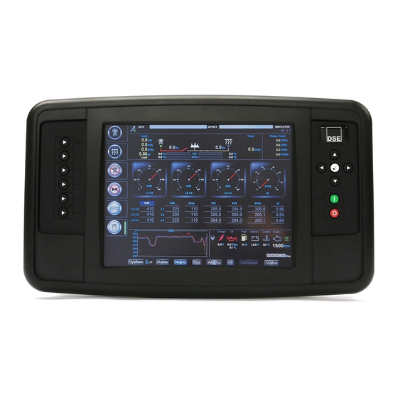
- Page 1 DEEP SEA ELECTRONICS PLC DSE8004 Operator Manual Document Number: 057-229 Author: Ashley Senior DSE8004 Operator Manual ISSUE: 2...
- Page 2 Applications for the copyright holder’s written permission to reproduce any part of this publication should be addressed to Deep Sea Electronics Plc at the address above. The DSE logo is a UK registered trademarks of Deep Sea Electronics PLC. Any reference to trademarked product names used within this publication is owned by their respective companies.
-
Page 3: Table Of Contents
DSE8004 Operator Manual TABLE OF CONTENTS Section Page BIBLIOGRAPHY ....................6 INSTALLATION INSTRUCTIONS ................ 6 MANUALS ......................6 INTRODUCTION ....................7 SPECIFICATIONS .................... 8 SHORT NAMES ....................8 OPERATING TEMPERATURE ................8 TERMINAL SPECIFICATION ................8 POWER SUPPLY REQUIREMENTS ..............8 3.4.1 MODULE SUPPLY INSTRUMENTATION DISPLAY ........ - Page 4 DSE8004 Operator Manual 4.1.5 RS232 CONNECTOR .................. 29 4.1.6 ETHERNET CONNECTOR ................30 TYPICAL WIRING DIAGRAM ................31 4.2.1 TYPICAL WIRING OF RS485 ..............31 CONFIGURATION (GRAPHICAL USER INTERFACE SETUP) ......32 DESCRIPTION OF CONTROLS ..............33 DISPLAY ......................34 5.1.1 SYSTEM OVERVIEW ..................
- Page 5 8.3.2 ACCESSING THE DSE8XXX CONTROLLER FRONT PANEL EDITOR OPERATION ......................76 MAINTENANCE, SPARES, REPAIR AND SERVICING ........ 77 PURCHASING ADDITIONAL CONNECTOR PLUGS FROM DSE ..... 77 9.1.1 INDIVIDUAL PLUGS ..................77 PURCHASING ADDITIONAL FIXING CLIPS FROM DSE ........77 PURCHASING ADDITIONAL SEALING GASKET FROM DSE ......77 WARRANTY ....................
-
Page 6: Bibliography
Bibliography 1 BIBLIOGRAPHY This document refers to and is referred to by the following DSE publications which can be obtained from the DSE website www.deepseaplc.com 1.1 INSTALLATION INSTRUCTIONS Installation instructions are supplied with the product in the box and are intended as a ‘quick start’... -
Page 7: Introduction
• R.O.C.O.F. and Vector shift for detection of mains failure when in parallel with the mains supply. Using a PC and the DSE SCADA Suite software allows alteration of graphical interface. Additionally, the DSE8004 integral front panel configuration editor allows adjustment of connected modules. -
Page 8: Specifications
Description DSE8004 -30 ºC to +70 ºC (-22 ºF to +158 ºF) 3.3 TERMINAL SPECIFICATION NOTE: For purchasing additional connector plugs from DSE, please see the section entitled Maintenance, Spares, Repair and Servicing elsewhere in this document. Description Specification Two part connector. -
Page 9: Digital Inputs/Outputs A To C
Specification 3.5 DIGITAL INPUTS/OUTPUTS A TO C 3.5.1 CONFIGURED AS INPUTS Description Specification Negative Switching Activation Connect the input terminal to the plant supply negative terminal Low Level Threshold 2.1 V minimum High Level Threshold 6.6 V maximum Maximum Input Voltage +50 V DC with respect to plant supply negative Minimum Input Voltage -24 V DC with respect to plant supply negative... -
Page 10: Communication Ports
Specification 3.7 COMMUNICATION PORTS NOTE: For further details of module configuration, refer to DSE Publication: 057-128 DSE8005 SCADA Suite Software Manual. NOTE: All communication ports can be used at the same time. Port Specification Type B USB 2.0 USB Slave Port... -
Page 11: Communication Port Use
NOTE: For further details of module configuration, refer to DSE Publication: 057-128 DSE8005 SCADA Suite Software Manual. NOTE: DSE stock 2 m (6.5 feet) USB type A to type B cable, DSE Part Number: 016-125. Alternatively, they are purchased from any PC or IT store. -
Page 12: Rs232 Port
Belden 9841 (or equivalent) cable. This allows for a large distance between the DSE8004 and multiple modules. 3.7.1.3.1 CABLE SPECIFICATION NOTE: DSE recommend Belden 9841 (or equivalent) cable for RS485 communication. This is rated to a maximum cable length of 1.2 km. DSE Stock Belden 9841 cable, DSE Part Number: 016-030. Description Specification... -
Page 13: Ethernet Port
RS232 connection method is more suitable and provides for a lower cost alternative to Ethernet (which is more suited to longer distance connections). NOTE: DSE stock 2 m (6.5 feet) Ethernet Cable, DSE Part Number: 016-137. Alternatively, they can be purchased from any PC or IT store. -
Page 14: Direct Module Connection
Specification 3.7.1.4.1 DIRECT MODULE CONNECTION Requirements • Crossover Ethernet cable (see Below) Crossover Ethernet Cable For the advanced Crossover Cable Wiring Detail Engineer, a crossover cable is a CAT5 cable Two pairs crossed, two pairs uncrossed with one end terminated 10baseT/100baseT crossover as T568A and the other end terminated as T568B. -
Page 15: Connection To Basic Ethernet
Specification 3.7.1.4.2 CONNECTION TO BASIC ETHERNET NOTE: DSE stock 2 m (6.5 feet) Ethernet Cable, DSE Part Number: 016-137. Alternatively, they can be purchased from any PC or IT store. Requirements • Ethernet cable (see below) • Working Ethernet (company or home network) -
Page 16: Connection To Company Infrastructure Ethernet
Specification 3.7.1.4.3 CONNECTION TO COMPANY INFRASTRUCTURE ETHERNET NOTE: DSE stock 2 m (6.5 feet) Ethernet Cable, DSE Part Number: 016-137. Alternatively they can be purchased from any PC or IT store. Requirements • Ethernet cable (see below) • Working Ethernet (company or home network) -
Page 17: Connection To The Internet
Specification 3.7.1.4.4 CONNECTION TO THE INTERNET NOTE: DSE stock 2 m (6.5 feet) Ethernet Cable, DSE Part Number: 016-137. Alternatively they can be purchased from any PC or IT store. Requirements • Ethernet cable (see below) • Working Ethernet (company or home network) •... -
Page 18: Firewall Configuration For Internet Access
DSE8005 SCADA Suite Software Manual. As modems or routers differ enormously in their configuration, it is not possible for DSE to give a complete guide to their use with the module. However it is possible to give a description of the requirements in generic terms. -
Page 19: Sounder
The audible alarm output activates and de-activates at the same time as the module’s internal sounder. The monitored DSE controllers alarm mute input and alarm mute button activate ‘in parallel’ with each other. Either signal will mute both the internal sounder and audible alarm output. -
Page 20: Dimensions And Mounting
Specification 3.9 DIMENSIONS AND MOUNTING 3.9.1 DIMENSIONS 405 mm x 241 mm x 51 mm (15.9” x 9.5” x 2.0”) 3.9.2 PANEL CUTOUT 359 mm x 204 mm (14.1” x 8.0”) 3.9.3 DISPLAY DIMENSIONS 210 mm x 160 mm (8.3” x 6.3”) 265 mm (10.5”) Diagonal Across Display. -
Page 21: Fixing Clips
Specification 3.9.5 FIXING CLIPS NOTE: In conditions of excessive vibration, mount the module on suitable anti-vibration mountings. The module is held into the panel fascia using the supplied fixing clips. • Withdraw the fixing clip screw (turn anticlockwise) until only the pointed end is protruding from the clip. -
Page 22: Silicon Sealing Gasket
Specification 3.9.6 SILICON SEALING GASKET NOTE: For purchasing an additional silicon gasket from DSE, please see the section entitled Maintenance, Spares, Repair and Servicing elsewhere in this document. The supplied silicon gasket provides improved sealing between module and the panel fascia. The gasket is fitted to the module before installation into the panel. -
Page 23: Applicable Standards
Specification 3.9.7 APPLICABLE STANDARDS Standard Description This document conforms to BS4884-1 1992 Specification for BS 4884-1 presentation of essential information. BS 4884-2 This document conforms to BS4884-2 1993 Guide to content BS 4884-3 This document conforms to BS4884-3 1993 Guide to presentation BS EN 60068-2-1 -30 °C (-22 °F) (Minimum temperature) -
Page 24: Enclosure Classifications
Specification 3.9.8 ENCLOSURE CLASSIFICATIONS 3.9.8.1 IP CLASSIFICATIONS The modules specification under BS EN 60529 Degrees of protection provided by enclosures IP65 (Front of module when module is installed into the control panel with the optional sealing gasket). IP42 (Front of module when module is installed into the control panel WITHOUT being sealed to the panel) First Digit Second Digit Protection against contact and ingress of solid objects... -
Page 25: Nema Classifications
Specification 3.9.8.2 NEMA CLASSIFICATIONS NOTE: There is no direct equivalence between IP / NEMA ratings. IP figures shown are approximate only. 3.9.8.2.1 THE MODULES NEMA RATING (APPROXIMATE) 12 (Front of module when module is installed into the control panel with the optional sealing gasket). 2 (Front of module when module is installed into the control panel WITHOUT being sealed to the panel) Provides a degree of protection against contact with the enclosure equipment and against a limited amount of falling dirt. -
Page 26: Installation
Installation 4 INSTALLATION The module is designed to be mounted on the panel fascia. To aid user connection, icons are used on the rear of the module to help identify terminal functions. An example of this is shown below. NOTE: Full details on terminals are provided in the section entitled Terminal Description elsewhere in this manual. -
Page 27: Rs485 & Rs485/Can Connector
Installation 4.1.2 RS485 & RS485/CAN CONNECTOR NOTE: For further details of module configuration, refer to DSE Publication: 057-128 DSE8005 SCADA Suite Software Manual. NOTE: A 120 Ω termination resistor must be fitted across terminals A and B if the DSE8004 is the first or last device on the R485 link. -
Page 28: Usb Slave (Firmware Update) Connector
USB devices to the PC. For further information, consult the PC supplier. NOTE: For further details of module configuration, refer to DSE Publication: 057-128 DSE8005 SCADA Suite Software Manual. NOTE: The USB connection cable between the PC and the module must not be extended beyond 6 m (20 feet). -
Page 29: Rs232 Connector
Installation 4.1.5 RS232 CONNECTOR NOTE: For further details of module configuration, refer to DSE Publication: 057-128 DSE8005 SCADA Suite Software Manual. NOTE: For further details on how utilise an RS232 connection, refer to section entitled Communication Port Usage elsewhere in this document. -
Page 30: Ethernet Connector
Installation 4.1.6 ETHERNET CONNECTOR NOTE: For further details of module configuration, refer to DSE Publication: 057-128 DSE8005 SCADA Suite Software Manual. Description Cable Socket for connection to an existing network to communicate Ethernet Cable to multiple DSE modules. View looking into the female connector on the module... -
Page 31: Typical Wiring Diagram
Installation 4.2 TYPICAL WIRING DIAGRAM 4.2.1 TYPICAL WIRING OF RS485... -
Page 32: Configuration (Graphical User Interface Setup)
Installation 4.3 CONFIGURATION (GRAPHICAL USER INTERFACE SETUP) NOTE: For further details of module configuration, refer to DSE Publication: 057-128 DSE8005 SCADA Suite Software Manual. The configuration is setup using the DSE8005 SCADA Suite PC Software in conjunction with a USB storage device. -
Page 33: Description Of Controls
Controls and Indications 5 DESCRIPTION OF CONTROLS The following section details the function and meaning of the various controls on the module. Together with the start and stop button, the six buttons to the left of the screen are used to provide control of the currently view DSE8xxx controller. -
Page 34: Display
Controls and Indications 5.1 DISPLAY 5.1.1 SYSTEM OVERVIEW Touch the screen or use the up/down arrow buttons to select the engine to control / monitor. The selected item appears with a blue border as shown below. The buttons to the left of the display change according to the selected controller. -
Page 35: Control Push-Buttons
Controls and Indications 5.2 CONTROL PUSH-BUTTONS 5.2.1 START/STOP BUTTONS Icon Description Stop / Reset Mode This button places the module into its Stop/Reset Mode . This clears any alarm conditions for which the triggering criteria have been removed. If the generator is running on load and the module is put into Stop/Reset Mode , the module automatically opens the generator bus breaker (‘Close Bus’... -
Page 36: When Connected To Dse8X10
Controls and Indications 5.2.2 WHEN CONNECTED TO DSE8X10 Icon Description Auto Mode This button places the module into its Auto Mode . This mode allows the module to control the function of the generator automatically. The module monitors various remote start functions and once a start request is made, the set is automatically started, synchronises and placed on load (‘Close Generator’... - Page 37 Controls and Indications Icon Description Open Generator The Open Generator button controls the operation of the generator load switch and is only active in Manual Mode once the generator bus is available. Synchronising NOT Enabled: Pressing the Open Generator button when the generator is available and on load causes the generator load switch to open (‘Close Generator’...
-
Page 38: When Connected To Dse8X20
Controls and Indications 5.2.3 WHEN CONNECTED TO DSE8X20 The function of the context buttons down the left side of the DSE8004 are indicated on the LCD display: Icon Description Auto Mode This button places the module into its Auto Mode . - Page 39 Controls and Indications Icon Description Test Mode This button places the module into its Test Mode . Once in Test Mode , the module responds to the Start button . Once the generator is available, it is automatically placed on load (‘Close Generator’...
- Page 40 Controls and Indications Icon Description Transfer to Mains The Transfer to Mains button control the operation of the mains load switching and is only active in Manual Mode once the generator bus is available. ‘Normal’ Breaker Button Control • Synchronising NOT Enabled: Pressing the Transfer to Mains button when the Mains is available and off load, the generator bus load switch is opened (‘Close Bus’...
- Page 41 Controls and Indications Icon Description Transfer to Generator The Transfer to Generator button control the operation of the mains load switching and is only active in Manual Mode once the generator bus is available. ‘Normal’ Breaker Button Control • Synchronising NOT Enabled: Pressing the Transfer to Generator button when the Generator is available and off load, the Mains load switch is opened (‘Close Mains’...
-
Page 42: When Connected To Dse8X60
Controls and Indications 5.2.4 WHEN CONNECTED TO DSE8X60 The function of the context buttons down the left side of the DSE8004 are indicated on the LCD display: Icon Description Auto Mode This button places the module into its Auto Mode . - Page 43 Controls and Indications Icon Description Test Mode This button places the module into its Test Mode . Once in Test Mode , the module responds to the Start button to send a start request to the DSE8x10 module over the MSC Link. The module monitors the MSC Link for feedback from the DSE8x10 module to confirm the generator bus is available.
- Page 44 Controls and Indications Icon Description Transfer to Mains The Transfer to Mains button control the operation of the mains load switching and is only active in Manual Mode once the generator bus is available. ‘Normal’ Breaker Button Control • Synchronising NOT Enabled: Pressing the Transfer to Mains button when the Mains is available and off load, the generator bus load switch is opened (‘Close Bus’...
- Page 45 Controls and Indications Icon Description Transfer to Generator Bus The Transfer to Generator Bus button control the operation of the mains load switching and is only active in Manual Mode once the generator bus is available. ‘Normal’ Breaker Button Control •...
-
Page 46: Viewing The Instrument
Controls and Indications 5.3 VIEWING THE INSTRUMENT PAGES It is possible to scroll to display the different pages of information by repeatedly operating the Next & Previous Page buttons. The currently selected page illuminates with Blue background. Example When Connected To DSE8x10 Controller Press the Next Page to view the next instrument page (Engine) etc. -
Page 47: Configurable Widgets
Touch the screen in the area of the Configurable Widgets to cycle through the different configured display options. The available displays are as shown in the examples below. This serves as an overview of that specific DSE Controller. Example of Chart Display... -
Page 48: Home Page
Controls and Indications 5.3.2 HOME PAGE The Home page of the view DSE8xxx controller is shown when no other page has been selected. It is also the page that is automatically displayed after a period of inactivity of the module control buttons. The parameters that are displayed changes dependent upon the DSE8xxx controller being viewed. -
Page 49: Summary Section
5.3.2.1 SUMMARY SECTION The content of the area is arranged as shown in the examples below. This serves as an overview of the viewed DSE Controller. Further information is viewed using the Instrument Pages as detailed below. 5.3.2.1.1 WHEN CONNECTED TO DSE8X10 CONTROLLER 5.3.2.1.2 WHEN CONNECTED TO DSE8X20 CONTROLLER... -
Page 50: Insturment Overview
5.3.2.2 INSTURMENT OVERVIEW The content of the area is arranged as shown in the examples below. This serves as an overview of the measured instruments of the viewed DSE Controller. Further information is viewed using the Instrument Pages as detailed below. -
Page 51: Engine
Controls and Indications 5.3.3 ENGINE NOTE: Not applicable to DSE8x60 modules. Contains instrumentation gathered about the engine which may be obtained using a CAN link. The content may change depending upon the selected engine and the features supported by the engine. To view additional pages within the current section, press the Instrumentation Scroll buttons. - Page 52 Controls and Indications The alarm icons above the instruments are shown as below: Parameter Inactive (Grey) Warning (Yellow) Shutdown (Red) Water In Fuel After Treatment Inlet Temperature Charge Alternator Oil Pressure Fuel Level Battery Voltage Coolant Temperature ECU Lamp CAN Link Unknown CAN Link Active CAN Link Lost Parameter...
-
Page 53: Generator
Controls and Indications 5.3.4 GENERATOR NOTE: Not applicable to DSE8x60 modules. The Generator section contains generator instruments measured from the viewed DSE controller. Press the Instrumentation Scroll buttons to cycle between the parameters. The instrumentation values are displayed in the form of either analogue meters or bar graphs depending on DSE8004 configuration. -
Page 54: Mains
Controls and Indications 5.3.5 MAINS NOTE: Not applicable to DSE8x10 modules. The Mains section contains generator instruments measured from the viewed DSE controller. Press the Instrumentation Scroll buttons to cycle between the parameters. The instrumentation values are displayed in the form of either analogue meters or bar graphs depending on DSE8004 configuration. -
Page 55: Bus
Controls and Indications 5.3.6 BUS NOTE: Not applicable to DSE8x20 modules. The Bus section contains generator instruments measured from the viewed DSE controller. Press the Instrumentation Scroll buttons to cycle between the parameters. The instrumentation values are displayed in the form of either analogue meters or bar graphs depending on DSE8004 configuration. -
Page 56: Alarms
Controls and Indications 5.3.7 ALARMS There are two screens on the alarms page, one displaying the current alarms and another displaying the event log. The alarms displays any current warnings, electrical trip and shutdown alarms and any CAN engine DTCs that are present. Engine alarms are not applicable when connected to DSE8x60 controller and only where connected to suitably configured CAN (ECU) engine. -
Page 57: I/O
Controls and Indications 5.3.8 I/O The I/O (Input/Output) section includes numerous screens that present the configuration and status of the inputs and outputs for DSE8xxx module and the DSE2130, DSE2131, DSE2133, DSE2152, DSE2157 and DSE2548 expansion units attached. Press the Instrumentation Scroll to cycle through the active I/O screens starting with the DSE8xxx’s Inputs followed by outputs and expansion modules. -
Page 58: Dse2130 Expansion Module
Controls and Indications 5.3.8.3 DSE2130 EXPANSION MODULE The DSE2130 screen displays the status of each DSE2130 device connected to the DSE8xxx module with the currently selected unit highlighted in blue. The alarm action is displayed when a Link Lost situation is present for the relevant unit. The Link lamp is green for good communication or grey for link lost. -
Page 59: Dse2133 Expansion Module
Controls and Indications 5.3.8.5 DSE2133 EXPANSION MODULE The DSE2133 screen displays the status of each DSE2133 device connected to the DSE8xxx module. The alarm action is displayed when a Link Lost situation is present for the relevant unit. The Link lamp is green for good communication or grey for link lost. For the selected DSE2133 unit, the screen shows the configuration description and the configuration description and current values of the analogue inputs. -
Page 60: Dse2157 Expansion Module
Controls and Indications 5.3.8.7 DSE2157 EXPANSION MODULE The DSE2157 screen displays the status of all attached DSE2157 device connected to the DSE8xxx module with the currently selected unit highlighted in blue. The alarm action is displayed when a Link Lost situation is present for the relevant unit. The Link lamp is green for good communication or grey for link lost. -
Page 61: Schedule
Controls and Indications 5.3.9 SCHEDULE This shows the current configuration of the DSE8xxx module’s scheduler. The scheduler configuration status is displayed on the top half of the screen. A title string (shown here as Scheduler Disabled) shows the scheduler enabled, mode and load configuration status and a table shows each scheduler entry details. -
Page 62: Status
Controls and Indications 5.3.10 STATUS 5.3.10.1 COMMUNICATION AND MODULE INFORMATION This page shows the status and configuration of the communication ports in use by the DSE8004. DSE8004 DSE8xxx Module Information Information 5.3.10.2 COMMISSIONING SCREENS An optional commissioning screen is available via an option in the running editor. When enabled, press the Instrumentation Scroll to change between the two pages. -
Page 63: Operation
Operation 6 OPERATION NOTE: For further details on module specific operation, refer to their operators manual. Refer to section entitled Bibliography elsewhere in the document for a list of applicable operators manual. The following description details the sequences followed by a module containing the standard ‘factory configuration’. -
Page 64: Quickstart Guide
Operation 6.1 QUICKSTART GUIDE This section provides a quick start guide to the module’s operation. 6.1.1 SELECTING THE ENGINE Touch the screen or use the up/down arrow buttons to select the engine to control / monitor. Example: 6.1.2 STARTING THE ENGINE Select the desired engine as shown above. -
Page 65: Stopping The Engine
6.2 MANUAL FUEL PUMP CONTROL NOTE: Manual fuel pump control is not applicable to DSE8x60 controller. • Navigate to the Engine Page (1/3) when viewing a DSE Controller using the Next & Previous Page buttons and locate Fuel Level. •... -
Page 66: Manual Speed Control
Operation 6.3 MANUAL SPEED CONTROL NOTE: Manual speed control is not applicable to DSE8x60 controller. • Navigate to the DSE controller and press and hold the Tick button to enter the Running Editor • Navigate to the Generator | Generator Frequency section •... -
Page 67: Protections
Protections 7 PROTECTIONS When an alarm is present, the Audible Alarm will sound and a marker is displayed next to the mute button. The audible alarm is silenced by pressing the Alarm Mute / Lamp Test button. The Alarm popup box is colour coded to indicate the level of the alarm. -
Page 68: Protections Disabled
The system designer provides this switch (not DSE) so its location will vary depending upon manufacturer, however it normally takes the form of a key operated switch to prevent inadvertent activation. Depending upon configuration, a warning alarm may be generated when the switch is operated. -
Page 69: Warnings
‘all warnings are latched’ will cause warning alarms to latch until reset manually. This is enabled using the DSE Configuration Suite PC Software with a DSE8xxx series controller. Not applicable to DSE8x60 controller : If the module is configured for, CAN and receives an “error”... -
Page 70: Front Panel Configuration
Front Panel Configuration 8 FRONT PANEL CONFIGURATION This configuration mode allows the operator limited customising of the way the module operates. Use the module’s navigation buttons to traverse the menu and make value changes to the parameters: Increase Value / Next Item Next Section... -
Page 71: Accessing The Dse8004 Running Editor
Front Panel Configuration 8.1 ACCESSING THE DSE8004 RUNNING EDITOR To enter the DSE8004 running editor, ensure the System page is being viewed with no DSE8xxx controller selected. The press and hold the Tick button to enter. When in the running editor mode, the instrumentation area of the screen is replaced with the running editor display, as shown below. - Page 72 Front Panel Configuration Section Parameter Selection Language English Configurable Language Display Pressure kPA, PSI or Bar Temperature ° F or ° C Units Litre, Gallons (US) or Volume Gallons (UK) Graphics Bars or Meters MM/DD/YYYY or Display Date Format DD/MM/YYYY Commissioning Screen Enable/Disable Backlight...
- Page 73 Front Panel Configuration Section Parameter Selection Communication Host IP Setup Host Port DHCP Enable Enable/Disable Host IP Subnet Mask Gateway IP DNS IP Advanced Inactivity Timeout Seconds Packet Timeout Milliseconds Multiset Control Enable/Disable MAC Address Sounder Multiset Sounder Enable/Disable Outputs Output A Output Source Communications Link Lost...
- Page 74 Front Panel Configuration Section Parameter Selection Time Module Time HH:MM:SS Module Date MM/DD/YYYY or DD/MM/YYYY Firmware Upgrade Version Layout Update Files Available Files...
-
Page 75: Accessing The Dse8Xxx Controller Running Editor
Front Panel Configuration 8.2 ACCESSING THE DSE8XXX CONTROLLER RUNNING EDITOR To enter the a DSE8xxx controller‘s running editor, ensure the System page is being viewed with the DSE8xxx controller selected or one of the DSE8xxx controller’s instrument pages. The press and hold the Tick button to enter. -
Page 76: Accessing The Dse8Xxx Controller Front Panel Editor Operation
Front Panel Configuration 8.3.2 ACCESSING THE DSE8XXX CONTROLLER FRONT PANEL EDITOR OPERATION When in the front panel editor, the display is arranged as shown in the figure below. The left segment shows the ‘title sections’, the middle segment shows the ‘sub sections’ and the right segment shows the editor items available within that ‘sub section’. -
Page 77: Maintenance, Spares, Repair And Servicing
In the case of malfunction, you should contact your original equipment manufacturer (OEM). 9.1 PURCHASING ADDITIONAL CONNECTOR PLUGS FROM DSE If you require additional plugs from DSE, please contact our Sales department using the part numbers below. 9.1.1 INDIVIDUAL PLUGS... -
Page 78: Warranty
Warranty 10 WARRANTY DSE provides limited warranty to the equipment purchaser at the point of sale. For full details of any applicable warranty, refer to the original equipment supplier (OEM). 11 DISPOSAL 11.1 WEEE (WASTE ELECTRICAL AND ELECTRONIC EQUIPMENT) If you use electrical and electronic equipment you must store, collect, treat, recycle... - Page 79 This Page is left blank intentionally...
- Page 80 This Page is left blank intentionally...
Need help?
Do you have a question about the DSEGenset DSE8004 and is the answer not in the manual?
Questions and answers