Table of Contents
Advertisement
Advertisement
Table of Contents

Summary of Contents for BellaVista 1000
- Page 1 Service Manual bellavista 1000/1000e Software Version V3.0 02.13 (in work)
- Page 3 Service Manual bellavista 1000/1000e...
-
Page 4: Table Of Contents
Table of contents Introduction ..............5 Description of the ventilator ........... 7 Maintenance Schedule ..........11 Software Upgrade ............13 Service Menu Overview ..........18 Shipment Test ............. 25 Annual Maintenance ........... 34 Electrical test ............... 57 Quick Check ..............62 Diagnosing and Repair .......... -
Page 5: Introduction
If possible, use original packaging maintenance tasks. Warning Never return bellavista uncleaned. According to the EU Directive, bellavista is classified as a Class IIb medical device. Preventive maintenance and calibration has to be performed Hotline according to the corresponding schedule (p. 11) - Page 6 Conditioning, cleaning and sterilising Clean and sterilize bellavista before and after each service task. Proceed as follows: Step Activity Turn off bellavista to prevent damage by pene- trating liquid. Clean surfaces incl. screen with a damp, lint- free cloth. The cloth should not be too wet! Never use abrasive cloth or cleaning agent.
-
Page 7: Description Of The Ventilator
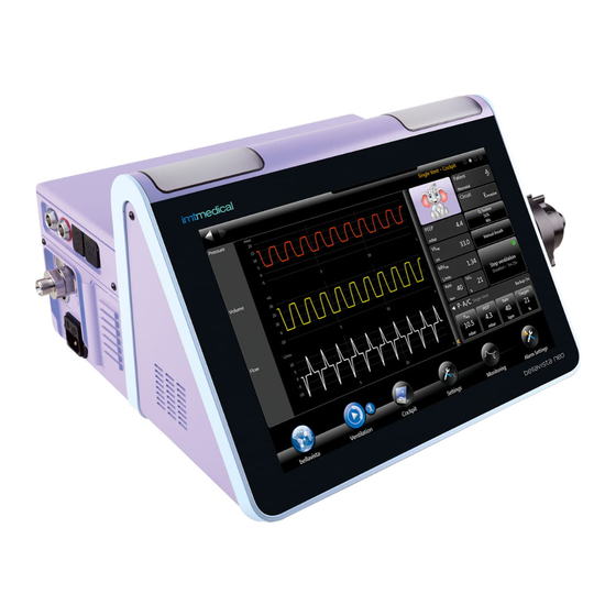
Screen with touch screen feature Cover for patient air filter Cover for external sensors Speaker Patient connectors At the bottom of bellavista, there are two slots for the storage of Speaker covers (3, 9) and access to the battery compartment. Cover bellavista bay... - Page 8 11 12 14 15 bellavista side panel right bellavista side panel left Description Connectors bellavista bus Description Nurse call Data storage (USB stick) 2x USB 2.0 Connection Assist Push button 100 MBit Ethernet network Connector for SpO sensor (optional) Connection Assist...
- Page 9 Airway pressure measurement Ambient pressure (barometer) O2 pressure regulation *) O2 safety valve Valve normally closed O2 proportional valve *) Valve normally open generation bellavista 1000 (SN: MB100001 … 99) O2 flow measurement*) *) not with 1 Rinse flow O2 cell...
- Page 10 (B4a) dPFlowProx (B18) Lifeboard (A8) Cable AC IN AC IN (X2) Cable Supply Cable Cable Powerboard (A2) Mushroom-Valve (Y6) Cable Bellavista bay Rinse-Valve (Y8) AC OUT Cable Cable Cable Rinse-Valve (Y7) Lifeboard bellavista bus Cable Cable Backlight Inverter DC_out...
-
Page 11: Maintenance Schedule
Maintenance Schedule 3. Maintenance Schedule Time interval Activity, Material Maintenance date, who Next maintenance n.a. n.a. Quick Check (p. 62) Requirement: Mandatory Weekly or Performed by: User before every Material: new patient New breathing circuit New patient air filter ... - Page 12 Maintenance date, who Next maintenance Software Upgrade (p. 13) ....................... When new After a software upgrade the users have to be trained regarding bellavista soft- the new functions and/or changes......................ware becomes Requirement: depends on separate communication...
-
Page 13: Software Upgrade
Download the upgrade onto the USB stick and install it on bellavista (p. 15) After completing the upgrade please upload the device information to the bellavista traceability data base (p. 16) The following chapters describe the above steps in detail. - Page 14 USB sticks. This directory and its content makes the USB stick “bellavista- ready”. It can be e-mailed or copied to other USB sticks. This is a bellavista LOG file. Please e-mail for trouble shooting.
- Page 15 Software Upgrade A valid upgrade is indicated with a new icon on the bellavista main screen Use iVista do download the upgrade Upgrade bellavista Download the upgrade Insert USB stick in bellavista Insert the USB stick into the computer running iVista.
- Page 16 Update the bellavista data base Background on Updates Insert the USB key into the bellavista unit you just upgrad- Content bellavista automatically stores the device information. Updates consist of one or multiple of the following elements. It Insert the USB stick into the computer running iVista.
- Page 17 B) If the update fails step b) try the following: Force the core process to install the update by keeping pressed both “Connection Assist” buttons while starting up bellavista.
-
Page 18: Service Menu Overview
Picture What to do / Protocol Login into Service level Password “service!” Danger Bellavista must not be used on a patient in service mode. After service level login restart bellavista before connecting it to a patient. 1 Versions Provides detailed information on software and printed circuit board versions. - Page 19 (averaging, filtering, calculation) Reset: Sets back all valves and special Some calibrations are grouped: executing the first means, you have to do them all, otherwise the calibration data is marked as invalid and bellavista becomes stops being opera- tional.
- Page 20 Picture What to do / Protocol 5 Output CFB Pneumatics Allows the controlling of all valves for diagnosing purpose. Caution Do not damage bellavista with unintended operation. 6 Output CFB Misc Allows the controlling of additional outputs for diagnosing purpose: ...
- Page 21 Service Menu Overview Picture What to do / Protocol 8 Audio / Alarming Allows the control and testing of the audio and visual alarming system. 9 Batteries Detailed information on the intelligent batteries. 10 Interfaces This screen is used to diagnose USB and internet interfaces.
- Page 22 Picture What to do / Protocol 11 External Sensors Tests the functionality of the external sensors and calibrates the CO2 Sensor. 13 Tests Self-test (page 1) Circuit test with detailed test results (page 2) Inspiration valve test (page 3) Note: do not perform the inspiration valve test unless ordered so by imtmedical staff.
- Page 23 5 Output CFB Pneumatics similar to but in a more flow-chart oriented way for diagnostics purpose. Caution Do not damage bellavista with unintended operation. 17 Factory Defaults Reset all previous user data (optional) Restart bellavista and go through the First Use Assist.
- Page 24 Picture What to do / Protocol 18 Alarms Detailed view and temporary disabling of all bellavista alarms (patient, user and technical). Go to active alarm to find active alarms in the list. Disabled alarms will automatically be enabled after restarting...
-
Page 25: Shipment Test
6. Shipment Test Scope: This checklist guides through tests which should be performed prior to shipping an already used bellavista to a cus- tomer (e.g. demo unit, rental). Some of the tests are optional and serve as a recommendation. Validity:... - Page 26 Login as service with password “service!” Select 17. Factory Default. This will do the following: History delete Device logs keep Trending data delete Settings set to factory defaults Profiles delete Restart bellavista and go through the First Use Assist.
- Page 27 Replace monthly ......replaced Yes No Dense layer inside .......... OK Cooling air filter (p. 64) Replace every 6 months ....replaced Yes No Startup bellavista bellavista startup without error messages or alarms.. OK...
- Page 28 Picture What to do / Protocol Software Configuration About bellavista Serial number: ............... Software Version: ..............Installed options DualVent™ Day/Night™ MaskFit™ WeanVent™ TargetVent™ Expert Ventilation Expert Monitoring ChameleonClassic™ ChameleonGreen™ Lung Mechanics ...
- Page 29 Gas type: Air / O2 Auto 4…7 bar Circuit Gas standard: AP21 Perform Zero! Calibration on Flow Analyser ALWAYS use a bacteria filter between bellavista and the FlowAnalyser Filter Connections according to picture Select breathing circuit C, non-invasive...
- Page 30 12 mbar, PEEP 5 mbar, Rate insp 12 bpm, Oxygen 21% / 35% / 70% (2 Generation only) Start ventilation for 60 sec before reading monitoring parameters: Expected PF-300 Bellavista 15…19 ( ....) ....Peak mbar 4…6 mbar PEEP ( ....
- Page 31 Shipment Test Picture What to do / Protocol Alarm Test Disconnect breathing circuit during ventilation Disconnect alarm should appear ...... OK Visual feedback (LEDs) .......... OK Acoustic feedback .......... OK Reconnect: alarm disappears ........ OK 11 External Sensors ...
- Page 32 Picture What to do / Protocol Touch Screen Check Back and Forward button on upper left corner can be pressed.............. OK Little dots in upper right corner can be pressed .. OK Battery Check ...
- Page 33 Shipment Test Picture What to do / Protocol Check completeness before delivery Bellavista SN: .............. Power cable Breathing Circuit(s): A C D with Flow Sensor Bacteria filter Spare filter set Easy Lung ...
-
Page 34: Annual Maintenance
Scope: This checklist guides through the annual maintenance procedure and serves as a protocol at the same time. Validity: For all bellavista 1000 G1 (some tests do not apply) and G2 Please send copy of checklist back to: imtmedical ag... -
Page 35: Spare Parts
Screwdriver size 5…6 Pressurized air 4…7 bar, up to 90 L/min Connection tube from pressurized air to DISS (or NIST, matching the bellavista configuration) USB 2.0 memory stick > 1GB Computer with Internet connection ... - Page 36 Warm up IMPORTANT: Switch-on FlowAnalyser and bellavista 30 min before the calibrations Switch-on bellavista and start ventilation for 30 min before the calibrations Clean bellavista (p. 6 ) Check completeness Bellavista SN: .............. Pulse Oxymeter (if applicable) ...
- Page 37 Replace 300.769.000 O2 Cell (see p 63) Replace 301.165.000 set of filter mats (see p 64) Open packaging of the new O2 cell 1 hour before inserting it into bellavista as the chemical O2 measurement process requires initiation.
- Page 38 The sinter metal filters are responsible for turbine cooling and have to be replaced annually as sometimes dust is accumulated. Position bellavista bottom down to prevent metal particles from falling into the turbine while replacing the sinter metal filter. 4. Calibrations: Blower Important: Don’t forget to execute...
- Page 39 Annual Maintenance Picture What to do / Protocol 15 Production Alarms Disable Ensure production alarms are ON (button shows prod. Alarms) Note: Production alarms are more narrow limits on many alarms. 1 Versions UI-Software: ................XP-Embedded: ............... Provides detailed information on software and printed cir- cuit board versions.
- Page 40 (averaging, filtering, calculation) Reset: Sets back all valves and special Some calibrations are grouped: executing the first means, you have to do them all, otherwise the calibration data is marked as invalid and bellavista becomes stops being operational.
- Page 41 Annual Maintenance Picture What to do / Protocol Zero pressure calibration This is a zero calibration of all pressure sensors. Disconnect all external tubing Perform the calibration Pressure gain calibration Calibrate the most important pressure sensors at 30 mbar in one calibration step.
- Page 42 Picture What to do / Protocol Zero calibration (Insp. Flow Sensor) This is a zero calibration of the differential pressure sensor of the inspiration flow measuring element. Disconnect all external tubing Perform the calibration After this calibration the “Invalid Calibration Data” Alarm will be active until the successful termination of the last flow scale point.
- Page 43 Annual Maintenance Picture What to do / Protocol Inspiration flow scale point calibration Calibrates the built-in patient flow sensor at the following flows. The flows are blower generated. Connections according to picture FlowAnalyser Setup ≤10 L/min in LF Low Flow setup. Read Flow L… L/min Set trigger to pediatric to enable Low Flow pressure compensation.
- Page 44 Picture What to do / Protocol O2 flow calibration This calibration consists of a number of sub-calibrations. If you perform the first one, you have to perform all the other calibrations as well, otherwise the entire calibration data will become invalid and the device stops being functional. 16 Function Blocks Caution Use the 2...
- Page 45 Annual Maintenance Picture What to do / Protocol O2 flow scale point calibration Not applicable for bellavista 1000 G1 Calibrates the built-in O2 flow sensor at the following flow points. Connections according to picture FlowAnalyser Setup or air 4…7 bar ...
- Page 46 Picture What to do / Protocol PWM blower calibration Automatically calibrates the PWM (pulse width modulation) of the blower. Disconnect all external tubing Perform calibration Blower reference calibration Calibrates the ratio blower input voltage to output pressure ...
- Page 47 Up to 90 L/min bration at 21% will be performed) Perform calibration. Ensure “two point calibration” has been performed. Otherwise warm up bellavista fur- ther and ensure appropriate O supply. Important: ...
- Page 48 Error! Reference source not found. See also (p. Error! Bookmark not defined.) Caution Do not damage bellavista with unintended operation. 6 Output CFB Misc Allows the controlling of additional outputs for diagnosing purpose: Nurse Call ...
- Page 49 Annual Maintenance Picture What to do / Protocol 7 Display / User Input Allows display and button diagnosing as well as touch screen calibration. If the touchscreen is severely de-calibrated: Use a USB-mouse to “feel your way”: press it to find out where it is, drag it away if you are on the wrong button ...
- Page 50 Calibrate the 4 corners (marked with arrows) Pay attention to the corners Calibrate from a normal user position (bellavista on trolley height, person standing in front). If you calibrate looking straight at the screen it may be inconvenient for the user.
- Page 51 Home care standards require battery support of ≥1 hour. Bellavista is equipped with 2 batteries with a nominal ca- pacity of 6450 mAh each (totally 12900 mAh) which last 4 hours. For security it is recommended to change a battery when it has reached ≤1/3 of its original capacity.
- Page 52 Use the built-in USB stick to check the functionality of all USB ports: Plug-out the USB stick on the right side of bellavista towards the back Plug-in the USB stick and ensure that it’s LED is flash- ing a few times: ...
- Page 53 Annual Maintenance Picture What to do / Protocol 13 Tests Self-test performs successfully. Note: do not perform the inspiration valve test on page 3 unless ordered so by imtmedical staff. Insp Valve Test On page three of 13 Test perform the Insp Valve Test. ...
- Page 54 FiO2 reading (98…100%) ..........% Check ambient pressure sensor 16 Function Blocks to compare “Press Ambient” with the measurement of the PF300 Press ambient (bellavista) ........mbar Pressure Atmospheric (PF300) ....... mbar Tolerance +/- ?? mbar...
- Page 55 Alarms) Electrical Safety Check electrical safety according to local regulations. Details see p. 57 Caution Do not test Protective Conductor Re- sistance as bellavista can be severely damaged. Quick Check Perform Quick Check See p.62 for details.
- Page 56 Picture What to do / Protocol Summary Yes No Test performed successfully: Technician: ................Place: ......... Date: ........Signature: ................
-
Page 57: Electrical Test
Bellavista is isolated and protects against electric shock and fulfills protective class I. Accessories (Applied Parts) are type BF. The ground concept of bellavista is according to the norm but slightly special as the Protective Conductor Resistance must not be measured. - Page 58 Nevertheless bellavista is not a class II device. Required material Use your electrical testing equipment Picture What to do / Protocol Visual Inspection Power cable insulation and connectors undamaged .. OK Sensor cable insulation and connectors undamaged .. OK All connectors visibly undamaged ........
- Page 59 Electrical Test Picture What to do / Protocol High Voltage Measurement Tests the insulation between mains terminals (L and N) against Protective Ground using 1500VAC or 2250VDC. No discharge within 60s .......... OK Leakage Current Measurement Earth Leakage Current <...
- Page 60 301.114.000 Diagnostic Package “Capnography” Patient Leakage Current AC < 0.10 mA .. OK Normal Condition Wrap sensors with 20 x 10 cm aluminum foil and connect to bellavista. The PLAC-NC < 0.50 mA .. OK Single Fault Condition wrapping simulates holding the sensor in a hand.
- Page 61 Electrical Test If you are running Secutest of www.gossenmetrawatt.com follow the following flow chart (from the original manual) Do not perform this test...
-
Page 62: Quick Check
12 ±1 bpm Connect power supply 1) Ventilation 21 vol% bellavista starts up without technical error. with ambient ± 2 vol% Optionally, connect oxygen supply Use fresh patient air filter 1) If not OK, calibrate O sensor (p. -
Page 63: Diagnosing And Repair
Diagnosing and Repair 10. Diagnosing and Repair Download LOG Files Bellavista creates LOG Files which protocol all user actions and Passwords program status. Warning During ventilation, do not log in as Insert a bellavista-ready USB stick into bellavista. 'service‘! bellavista automatically stores LOG files and identification information. - Page 64 Danger A dirty or wrong patient air filter can lead to undersupply of the patient. Danger Only use original bellavista air filters. Caution Missing, wrong or dirty air filter can lead to Danger Calibrate FiO sensor regularly (p. 46).
-
Page 65: Battery Replacement
Diagnosing and Repair Battery replacement Replacing O2 Inlet Filter Danger Never attempt to disconnect or connect the A replaceable metal mesh battery during operation. filter situated behind the DISS or NIST Adapter protects the O2 Inlet from dust. However Battery check see p. 51 this is just a safety filter. - Page 66 60% through the blower) at 82°/92°. There is a bypass cooling-flow exiting bellavista through two Blower temperature can be observed in the service level under sinter metal filters at the bottom. This bypass flow sufficiently 16 Function Blocks.
- Page 67 Diagnosing and Repair Step Action Check Inspiration Block Leakage Slowly set the “blower voltage” up, until “press This procedure helps to diagnose leakage of the inspiration Blower” reaches 38mbar block. (Important not to go higher) Step Action Protocol “Flow Insp”: ......L/min Start up device, allow 30 minutes warm up time.
- Page 68 Step Action Switch off bellavista and restart it, if needed. Press “Start Insp Valve Test” : This self test takes a few minutes. Some alarms will occur. After test please send a picture of the screen.
- Page 69 Pressure controller Disconnect all pneumatical tubes. Pressure 30 mbar Flow 0 L/min Log on in service level. Mushroom Valve 1000 2 ADCs Go to Step Action Step Action 2 ADCs Go to service menu Check value of Dp flow prox: .......
- Page 70 Check Internal Flow Measurement Step Action For this check, you need two bellavistas, a “Good” one and a Connect blue tube on white connector potentially “Bad” one. Check value of Dp flow prox ......Step Action Start up devices, allow 30 minutes warm up time.
- Page 71 Diagnosing and Repair Check O valve leakage Step Action Step Action 16 Func- In “Bad” Device go to service menu Start up device, allow 30 minutes warm up tion Blocks time. Connect oxygen supply Slide to Page 2 => Service controller, Set: ...
- Page 72 After one Minute, take a screenshot Name it “Position 9” Switch O2 Safety valve to OFF After one Minute, take a screenshot. Name it “Position 10” Download the log files (see p. 14) Send screenshots and log files for analysis. Restart bellavista...
- Page 73 Diagnosing and Repair How to Open bellavista Step Action Step Action Unscrew the 11 bottom screws (don’t unscrew Disconnect power supply Work in anti-static protected environment with other than this marked screws) anti-static connection also for the service engi- neer.
- Page 74 Cables Step Action Slowly pull up the back cover of bellavista and turn it to the back. Take care about the FAN- cable at the backside! Store Back cover at the edge side to protect against scratch’s. Cable...
- Page 75 Diagnosing and Repair Step Action Step Action If the front cannot be pulled away, slightly Display cable: Hold band with two fingers and loosen the 6 screws at the bottom only 1 turn. pull the display cable with the third finger. Do not remove these screws! Hold Pull...
- Page 76 Action Disconnect power supply Work in anti-static protected environment with anti-static connection for the service engineer. Backlight Inverter Open bellavista (p. 73) Disconnect all cable plugs to the backlight inverter Unscrew the two screws Exchange the part Connect the Cables...
- Page 77 Diagnosing and Repair Assembly of Trolley 301.105.000...
- Page 78 Extreme ventilation settings Patient air filter blocked Blower cooling filter blocked Remedies bellavista automatically reduces FiO2 to prevent further increase of tem- perature. Further actions: Reduce O2 concentration manually Move to cooler environment ...
- Page 79 Diagnosing and Repair Message Reason, Remedy 237 Temperature of device CPU high Reason Ambient temperature very high Ventilator air filter blocked Remedy Move to cooler area Replace ventilator air filter If it is a recurring error, notify service technician 238 Temperature of device too high Reason ...
- Page 80 Blower cooling filter blocked Warning: if the temperature increases further, the ventilator could be damaged or destroyed Remedy bellavista automatically reduces FiO2 to prevent further increase of tem- perature. Further actions: Reduce O2 concentration manually ...
- Page 81 306 Technical failure 306 - Sound system broken The microphone has not detected the alarm sound. Possible reason: no alarm sounded (loudspeaker broken) or microphone broken. Very rarely this can be due to noisy environment (exhibition) Restart bellavista.
- Page 82 In some cases it may help to “warm up” the buzzer by operating it for a cou- 8 Audio / Alarming ple of minutes using Restart bellavista. 314 Technical failure 314 - Loudspeaker test failed During the selftest the microphone has not detected the alarm sound.
- Page 83 9 Batteries operation possible - do not disconnect mains supply! Note: when connected to mains power suppy at all times, bellavista may be used with only one battery. 321 Technical failure 321 - Battery disconnected - no The battery is not plugged in correctly or is possibly defective. Plug in and battery operation possible - do not disconnect restart bellavista.
- Page 84 Message Reason, Remedy 332 Technical failure 332 - 3.3V voltage low 334 Technical failure 334 - 3.3V voltage high 335 Technical failure 335 - 5V voltage low 336 Technical failure 336 - 5V voltage high 337 Technical failure 337 - 9V voltage too low 338 Technical failure 338 - 9V voltage too high 339 Technical failure 339 - 12V voltage low 340 Technical failure 340 - 12V voltage too low...
- Page 85 An internal O2 overpressure was detected: PO2Regulated (which should be ≤2.5 bar) is higher than 3.5bar. Possible cause: Leaking of O2 pressure regulator. Try to connect O supply only after starting up bellavista. aTf_388HighPressO2RegulatedMessage 389 Technical failure 389 - No O2 dosing possible The O safety valve may be leaking.
- Page 86 Message Reason, Remedy 504 Technical failure 504 - Assertion id machine states 505 Technical failure 505 - Assertion id monitors 506 Technical failure 506 - Assertion id curves 507 Technical failure 507 - Assertion id breath moni- tors 508 Technical failure 508 - Assertion id actuators 514 Technical failure 514 - Scaled periphery sensor value out of range 515 Technical failure 515 - Scaled ventilation sensor...
- Page 87 Diagnosing and Repair Message Reason, Remedy 534 Technical failure 534 - Vd interrupt runtime ex- ception catched 535 Technical failure 535 - Unknown exception in tasking catched 536 Technical failure 536 - Unknown exception in vd interrupt catched 540 Technical failure 540 - Scaled periphery sensor value out of range - failsafe 542 Technical failure 542 - Scaled ventilation sensor value out of range - failsafe...
- Page 88 Message Reason, Remedy 557 Technical failure 557 - ADC 4, rTempLifeboard- Scaled value out of range 558 Technical failure 558 - ADC 4, rPressFlowProx- Scaled value out of range 559 Technical failure 559 - ADC 4, rPressMush- roomControlScaled value out of range 560 Technical failure 560 - ADC 4, rFlowProxScaled value out of range 566 Technical failure 566 - PWM, aPwmVolt-...
- Page 89 Diagnosing and Repair Message Reason, Remedy aTf_577TechnicalFailureRTempO2Scaled1000G2ValueOutOfValidRangeMessage 577 Technical failure 577 - value out of range 578 Technical failure 578 - value out of range aTf_578TechnicalFailureRTempInspScaled1000G2ValueOutOfValidRangeMessage 580 Technical failure 580 - Qspi interrupt catched runtime exception 581 Technical failure 581 - Qspi interrupt caught unknown exception 582 Technical failure 582 - I2C interrupt catched runtime exception...
- Page 90 Message Reason, Remedy 8 Audio / Alarming 998 Test alarm (medium priority) Test alarm which can be activated in 8 Audio / Alarming 999 Test alarm (info priority) Test alarm which can be activated in...
-
Page 91: Spare Parts
Leak adapter for use with test lung and breathing circuit 301.557.000 Filter Element 5um 301.115.000 Connector for curse call 301.260.000 Metal Filter Insert O2 Input 301.116.000 Connector for bellavista Bus 100.075.100 Sinter metal filter 301.110.000 Connector for 24 V feed 301.102.000 Housing cover alarm 301.159.000 Accessory bag 301.038.000... - Page 92 Art No Designation Technical Spare Parts 300.788.000 Backlight inverter 301.004.100 Blower module 301.069.000 CFB controller board 301.080.000 Embedded PC 300.907.000 Fan with cable 301.051.100 Inspiration valve 300.914.000 Interface board 300.852.000 LED board 300.844.000 Lifeboard 300.833.000 Main board 300.924.000 Mushroom valve 301.085.000 Packaging 300.886.000...
-
Page 93: Index
Electrical test Quick Check install pneumatics filter mats selftest USB stick calibrations replacing Shipment Test bellavista ready blower fuse Software Upgrade device information flow G1, G2 spare parts files flow O2 blender hotline sterilising update data mushroom (exp.) valve...
Need help?
Do you have a question about the 1000 and is the answer not in the manual?
Questions and answers