
Summary of Contents for Cooper safety CEAG EURO ZB.1
- Page 1 Mounting and Operating Instructions EURO ZB.1 EURO US.1 Target group, part 1: Qualified electrician acc. to DIN VDE 0105, part 1 Target group, part 2: Electrical instructed persons...
-
Page 2: Table Of Contents
Mounting and Operating Manual Central Battery System EURO ZB.1 Table of contents Part 1 Important Notes Product Description Technical Data Batteries for Emergency Power Supply Tending and Checking Batteries Modules Functioning Functions Battery Control Module BCM Functions Charging Module CM 1.7 A and CM 3.4 A Functions of DC/DC converter.2 Functions of the ST 20 E Control Unit Function of Circuit Changeover SKU 2 x 3 A... - Page 3 Mounting and Operating Manual Central Battery System EURO ZB.1 Table of contents Commissioning and Further Work 12.1 Disconnecting/Switching-on an Emergency Lighting System under Battery Supply 12.2 Disconnecting/Switching-on a EURO ZB.1 or EURO US.1 control cabinet 12.3 Block/Release the Control of a EURO ZB.1 or EURO US.1 control cabinet 12.4 Checking all Connections / Insulation Testing 12.5 Testing / Replacing Fuses...
-
Page 4: Important Notes
Mounting and Operating Manual Central Battery System EURO ZB.1 Important Notes Important Notes Mounting work must only be carried Warning! out by skilled electrical personnel (see The figures and elementary IN VDE 0105 Part 1; the Accident Pre- diagrams in this mounting and vention Rules BGV A4 of the (German) operating manual sometimes Trade Workers’... -
Page 5: Product Description
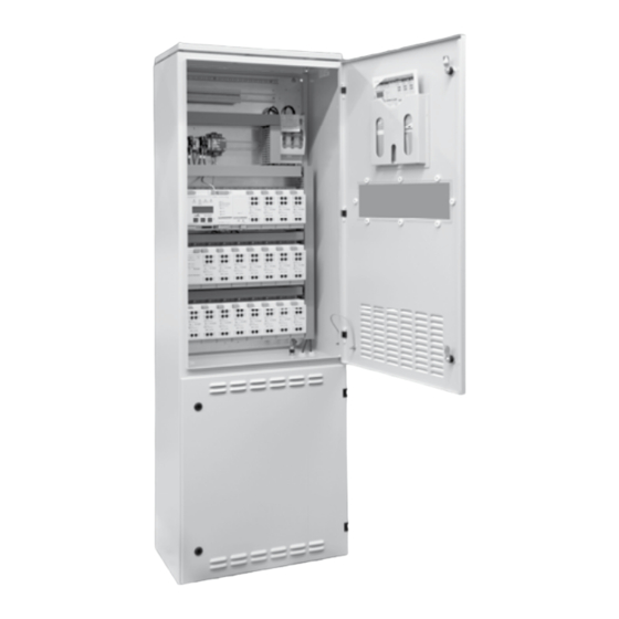
Mounting and Operating Manual Central Battery System EURO ZB.1 Product Description Product Description The central battery system serves for Low-maintenance batteries are used the battery-backed control and emer- to power the emergency lighting gency supply of an emergency lighting system in the event the normal 230 V system. - Page 6 Mounting and Operating Manual Central Battery System EURO ZB.1 Product Description Fig. 1: EURO ZB.1 of type EURO To suit local conditions a number of diffe- Notes: ZB.1/200S and for operation with a rent system configurations are employed. Planning and design information battery capacity of up to 240 Ah and These standardized configurations are can be seen from the CEAG catalog...
- Page 7 Mounting and Operating Manual Central Battery System EURO ZB.1 Product Description The following supplementary functions Functional monitoring via a higher- can be realized: ranking supervision system. For this purpose CEAG emergency Connecting CEAG 3-phase detectors lighting systems offer a CG controller (3PhW) to monitor the general supply or the CG Vision supervisory system.
- Page 8 Mounting and Operating Manual Central Battery System EURO ZB.1 Product Description Fig. 3: Example of a control cabinet layout (EURO ZB.1/52) Frontansicht geöffnet Innere Seitenansicht links Innere Seitenansicht rechts ESCH E-G-A Filter ST20 ZB96 kpl BGT1 11 12 21 31 32 + - U1 01 U2 02 U1 01 U2 02 U1 01 U2 02...
- Page 9 Mounting and Operating Manual Central Battery System EURO ZB.1 Product Description Fig. 4: Detail view of control unit, DC/DC converter, charging unit and SKU circuit changeover ST20 ZB96 kpl BGT1 11 12 21 31 32 + - U1 01 U2 02 U1 01 U2 02 U1 01 U2 02 Netz...
- Page 10 Mounting and Operating Manual Central Battery System EURO ZB.1 Product Description Fig. 8: Detail view of control unit ST 20 E (terminal blocks on module serve to facilitate mounting and removal ov the module. 1: Control unit housing 6: LC backlit display (4 lines, 20 cha- 10: LEDs for operating status indica- racters each) tion...
-
Page 11: Technical Data
Mounting and Operating Manual Central Battery System EURO ZB.1 Technical Data Technical Data Fig. 9: Inside view of EURO ZB.1/52 EURO ZB.1 Control Cabinet EURO ZB.1/52 Rated operating voltage: 400/230 V 50 Hz Frontansicht geöffnet re Seitenansicht links Innere Seitenansicht rechts Control unit EURO ZB.1 ESCH DC/DC converter.2... - Page 12 Mounting and Operating Manual Central Battery System EURO ZB.1 Technical Data Compact Control Cabinet EURO ZB.1/20K /26K /188K /18K Fig. 9a: Inside view of Rated operating voltage: --------------- 230 V 50 Hz ---------------- EURO ZB.1/188K Frontansicht geöffnet (ohne Batterie) Innere Seitenansicht rechts Control unit EURO ZB.1 DC/DC converter.2 Battery Control Module BCM...
- Page 13 Mounting and Operating Manual Central Battery System EURO ZB.1 Technical Data Fig. 9a: Inside view of Compact Control Cabinet EURO ZB.1/204K /264K EURO ZB.1/204K Rated operating voltage: --------------- 230 V 50/60 Hz--------------- Control unit EURO ZB.1 Seitenansicht links Innere Seitenansicht rechts Frontansicht geöffnet (ohne Batterie) DC/DC converter.2 BGT1...
- Page 14 Mounting and Operating Manual Central Battery System EURO ZB.1 Technical Data Fig.11: Inside view of EURO US.1/72 Substation EURO US.1 EURO US.1/72 EURO US.1/42 Rated operating voltage: ----------- 230 V 50/60 Hz ------------- Control unit ST 20 E DC/DC converter (model DC/DC.2) 1 - 2 Circuit module SKU 0 - 36...
- Page 15 Mounting and Operating Manual Central Battery System EURO ZB.1 Technical Data Substation EURO US.1 EURO US.1/26 /10 /ESF-E30/17 ESF-E30/28 Rated operating voltage: -------------------------- 230 V 50/60 Hz ------------------------ Control unit ST 20 E DC/DC converter (model DC/DC.2) Circuit module SKU 0 - 13 0 - 5 0 - 17...
-
Page 16: Batteries For Emergency Power Supply
Mounting and Operating Manual Central Battery System EURO ZB.1 Batteries Batteries for Emergency Power Supply CEAG offers battery cabinets of various sizes and accommodating various compo- nents. Low-maintenance batteries according to EUROBAT standard are provided the service life of 10 years if handled and operated properly and with circum- spection. -
Page 17: Tending And Checking Batteries
Mounting and Operating Manual Central Battery System EURO ZB.1 Batteries Tending and Checking Batteries Inspection The following minimum inspection instructions must be observed to ensure the full service life of the batteries. In case of records being incomplete and/or failure to carry out battery inspections the warranty may become void or legally ineffective. -
Page 18: Modules Functioning
Mounting and Operating Manual Central Battery System EURO ZB.1 Modules Modules Functioning Functions of Batterie Control Modul BCM Indicators ON LED The LED lights up when the BCM is in operation. If the LED does not light up then the BCM is faulty or there is no mains supply or a function test has been triggered. -
Page 19: Functions Of Dc/Dc Converter.2
Mounting and Operating Manual Central Battery System EURO ZB.1 Modules Functions of the DC/DC converter.2 This module supplies 24 V- and 6 V direct Additional features: voltage to the central battery system. External 24 V – 20 W continuous rating Light-emitting diodes –... -
Page 20: Functions Of The St 20 E Control Unit
Mounting and Operating Manual Central Battery System EURO ZB.1 Modules Fig. 13: Components of ST 20 E control unit Functions of the ST 20 E Control Unit Freely programmable control with non-volatile program memory for progamming and user-specific paramete- rization purposes. Internal log book recording The ST 20 E control unit saves the log book as per DIN VDE 0108 specificati-... -
Page 21: Function Of Circuit Changeover Sku 2 X 3 A
Mounting and Operating Manual Central Battery System EURO ZB.1 Modules Functions of Circuit Changeover SKU 2 x 3 A Fuses Additional features On the circuit changeover unit’s faceplate 3 outgoing fuses 5 AT / 250 V are ar- Changing over individual circuits ranged for each circuit. -
Page 22: Function Of Circuit Changeover Sku 1 X 6 A
Mounting and Operating Manual Central Battery System EURO ZB.1 Modules Functions of Circuit Changeover SKU 1 x 6 Fuses Additional features On the circuit changeover unit’s face- Separate fuse protection for mains plate 3 outgoing fuses 10 AT / 250 V are arranged. -
Page 23: Function Of Circuit Changeover Sku 4 X 1 A
Mounting and Operating Manual Central Battery System EURO ZB.1 Modules Functions of Circuit Changeover SKU 4 x 1 A Fuses Additional features Individual monitoring On the circuit changeover unit’s facepla- te 8 outgoing fuses 1.6 AT / 250 V are of a maximum of 20 luminaires arranged. -
Page 24: Circuit Changeover Units At A Glance
Mounting and Operating Manual Central Battery System EURO ZB.1 Modules Circuit Changeover Units at a Glance At the present time the following SKU modules are available for the EURO ZB.1 system: SKU 2 x 3 A EURO ZB.1 new! Number of circuits 2 w/o switching function for CG-S-EVGs Rated current per circuit 3 A Dimensions and weight... -
Page 25: Functions Of Event Printer Pd
Mounting and Operating Manual Central Battery System EURO ZB.1 Modules Functions of Event Printer PD 2 Description Control This module is a 4-dot matrix printer for Printer function alphanumeric characters, line width is 24 An event can be printed after the relevant characters. -
Page 26: Print-Out - Event Printer Pd 2
Mounting and Operating Manual Central Battery System EURO ZB.1 Modules 5.10 Print-out - Event Printer PD 2 Print-out BGT 2 Subrack 2 Function test Date: dd.mm.yy Slot 07 7th circuit changeover Time: hh.mm Charging current = ...A Circuit 02 = 2nd circuit Ubatt = ...V Isolation o.k. -
Page 27: Function Of The Relay Module (Cg Iv)
Mounting and Operating Manual Central Battery System EURO ZB.1 Modules 5.11 Function of the Relay Module CG IV Connection Relay module CG IV This subassembly allows the connection of the central battery system to a central control station (ZLT) or building manage- ment system (BMS). -
Page 28: Functions Of The Tls Switching Module
Mounting and Operating Manual Central Battery System EURO ZB.1 Modules 5.12 Functions of the TLS Switching Module Description TLS switching module If general and safety luminaires are to be This module enables time-controlled switching (1 to 15 minutes) of the final controlled by the same buttons (without circuits during mains and battery opera- additional installation expense) a TLS... -
Page 29: Function Of The Dls Switching Module
Mounting and Operating Manual Central Battery System EURO ZB.1 Modules 5.13 Functions of Permanent Light Switch Checking Description Application: Installation in the EURO ZB.1 This electronic monitoring module serves for (light) switch checking purposes. (EURO US.1) control cabinet During mains operation luminaires of the to facilitate maintenance efforts general and safety lighting systems are Notes:... -
Page 30: Functions Of The Sds 8 Switching Module
Mounting and Operating Manual Central Battery System EURO ZB.1 Modules 5.14 Functions of the SDS 8 Switching Module Application example Description Two distributors of the general power Monitoring module SDS 8 is an optional supply system shall be supervised component that can be mounted in the such that if one of the distributors central battery system. -
Page 31: Block Diagram
Mounting and Operating Manual Central Battery System EURO ZB.1 Block diagram CEAG Notlichtsysteme GmbH... -
Page 32: Installation Example Euro Zb.1
Mounting and Operating Manual Central Battery System EURO ZB.1 Installation Example Euro ZB.1 UVA 1 Batt. Attention! Only one temperature sensor must be con- nected! F+ F- PE B+ B- PE N L1 L2 L2- L3 3PH-Uberw. 2 3 4 1 2 3 S -S External phase... -
Page 33: Installation Example Euro
Mounting and Operating Manual Central Battery System EURO ZB.1 Installation Example Euro US.1 External phase monitor General lighting Loop open = Maintained light Loop closed = Non maintained light Circuit on Maintained light Circuit on switched Non maintained light via SDS 8 Euro US.1 Battery feed-in Mains feed-in... -
Page 34: Important Notes On Safety At Work And Safe Operation Of The Emergency Lighting System Euro
Mounting and Operating Manual Central Battery System EURO ZB.1 Important Notes on Safety at Work and Safe Operation of the Emergency Lighting System EURO ZB.1 Important Notes on Safety at Work and Safe Opera- tion of the Emergency Lighting System EURO ZB.1 Warning! –... -
Page 35: Intended Use
Mounting and Operating Manual Central Battery System EURO ZB.1 Intended Use Intended Use The central battery systems EURO ZB.1 Nevertheless, danger may arise during and EURO US.1 are intended for moni- plant operation toring and controlling lighting plants for to personnel if the safety instructions general and emergency lighting purpo- are disregarded, ses. -
Page 36: Transport, Storage And Disposal
Mounting and Operating Manual Central Battery System EURO ZB.1 Transport, Storage and Disposal Transport, Storage and Disposal The batteries for safety lighting purposes – have adequate carrying capability are supplied together with the battery (for load, transport packing and cabinets employed. transportation means), As regards transport and storage of the and that the transport routes are sui-... -
Page 37: Mounting
Mounting and Operating Manual Central Battery System EURO ZB.1 Mounting Mounting Danger! When delivered to the customer the When batteries or battery-fed equipment shown in this mounting and parts of the system are impro- operating manual may differ in terms of modules fitted. -
Page 38: Mounting The Control Cabinet
Mounting and Operating Manual Central Battery System EURO ZB.1 Mounting the Control Cabinet Installation of General and Emergency Lighting Sy- stems 10.1 Mounting the Control Cabinet Fig. 18: Overview of the control cabi- The control cabinets must be mounted Do not allow connecting lines/leads net with top PE terminal block (1) for on level and sustainable ground (adequa- to be laid loosely in a make-shift... -
Page 39: Mains Connections To Substations Euro Us.1
Mounting and Operating Manual Central Battery System EURO ZB.1 Connection of the Mains Power Supply to EURO ZB.1 Mains Connections to Substations EURO US.1 Fig. 19: Position of load-break switch Example 2: 11.2 Mains Connec- (1) (terminal and fuse box for mains ZB-S 10C3 with 17 circuits and 10 lumi- tions to Substations power supply) and terminal blocks (2) -
Page 40: Connecting The Battery Supply
Mounting and Operating Manual Central Battery System EURO ZB.1 Connecting the Battery Supply Fig. 22: Connections with load-break 11.3 Connecting the Battery Supply switch cover removed Item 1: Connection lines for conductor Observe the data sheets of the battery Only one temperature sensor rail (mains) located behind manufacturer CEAG has included in the (F+ / F-) must be connected to the... -
Page 41: Connecting The Battery Supply Of A Euro Zb.1 Station
Mounting and Operating Manual Central Battery System EURO ZB.1 Connecting the Battery Supply Abb. 25: Location of the load-break 11.4 Connecting the 11.5 Connecting the switch Supply of a EURO ZB.1 Supply of a EURO US.1 Item 1: Location of load-break switch Station Substation for battery supply... -
Page 42: Connection Of A Temperature Sensor
Mounting and Operating Manual Central Battery System EURO ZB.1 Mounting and Connection of a Temperature Sensor Mounting and Connection of Internal Modules Fig. 27: Position of the terminal block 11.6 Connection of a 11.7 Mounting and Con- for connection PE terminals of final Temperature Sensor nection of Internal circuits in a EURO ZB.1 control cabinet... -
Page 43: Connection Of Dls Modules
Mounting and Operating Manual Central Battery System EURO ZB.1 Connection of a DLS Module Fig. 29: DLS module 11.8 Connection of a DSL Module For each switching command a line must be laid between control cabinet (EURO ZB.1 or EURO US.1) and the distributor for the mains supply (of the circuits monitored). - Page 44 Mounting and Operating Manual Central Battery System EURO ZB.1 Connection of an SDS Module Fig. 32: SDS module with terminal assignment on module (top/bottom) 11.9 Connection of SDS 8 Module For each switching command a line must be laid between control cabinet (EURO ZB.1 or EURO US.1) and the distribu- tor for the mainsr supply (of the circuits monitored).
-
Page 45: Connection Of Tls Modules
Mounting and Operating Manual Central Battery System EURO ZB.1 Connection of a TLS Module Fig. 34: TLS module with terminal as- signment on module (top/bottom) 11.10 Connection of TLS Modules The staircase lighting switching mode No. of switches per TLS input: must be programmed via the freely Mom. -
Page 46: Mounting And Connection Of Ceag 3-Phase Monitors With 24 V Loop
Mounting and Operating Manual Central Battery System EURO ZB.1 Mounting and Connection of a CEAG 3-phase monitor with 24 V loop Fig. 36: 11.11 Mounting and Connection of a CEAG 3-phase CEAG 3-phase monitor monitor with 24 V loop These devices are of slide-on built-in Connection in control cabinet EURO type for mounting in a control cabinet/ ZB.1 (EURO US.1) is effected on a con-... -
Page 47: Connection Of A Remote Switch/F3 Module
Mounting and Operating Manual Central Battery System EURO ZB.1 Connection of a Remote Switch/F3 Remote Indicating Unit - Completing Mounting Work Fig. 39: Remote switch/F3 module 11.12 Connection of a Remote Switch/F3 Remote Indi- cating Unit Connections are made as per Figure Completing Mounting Work 40 (single-line diagram) as well as field installation diagrams and drawings. -
Page 48: Commissioning And Further Work
Mounting and Operating Manual Central Battery System EURO ZB.1 Commissioning and Further Work Commissioning and Further Work Warning! Attention! Commissioning or re- Never switch the mains starting (after retrofitting or or battery supply on or off maintenance/repairs) of the under load. -
Page 49: Disconnecting/Switching-On An Emergency Lighting System Under Battery Supply
Mounting and Operating Manual Central Battery System EURO ZB.1 Disconnecting/Switching-on an Emergency Lighting System under Battery Supply 12.1 Disconnecting/Switching-on an Emergency Lighting System under Battery Supply Danger! Before re-connecting the battery sup- Turning the mains supply on or ply at the connections of the battery off within the pertinent distributor bank switch on the mains power should never take place under... -
Page 50: Checking All Connections / Insulation Testing
Mounting and Operating Manual Central Battery System EURO ZB.1 Checking the Connections Insulation Testing Fig. 42: Insulation Testing 12.4 Checking all Con- Insulation testing nections 42 a: Extract terminal block (1) and Check whether the entire system has short circuits (2) been disconnected and take safety ... -
Page 51: Testing/Replacing Fuses
Mounting and Operating Manual Central Battery System EURO ZB.1 Testing / Replacing Fuses 12.5 Testing/Replacing Fuses The fuses for mains and battery supply Testing the fuses on SKU modules are arranged in the pertinent load-break switches (Fig. 3, Items 9 and 11) or on For safety reasons all SKU modules the battery bank. -
Page 52: Checking And Replacing Modules
Mounting and Operating Manual Central Battery System EURO ZB.1 Checking and Replacing Modules Fig. 44: SKU 2 x 3 A 12.6 Checking and Replacing Modules Attention! Checking and replacing control unit, SKU modules must never be DC/DC converter or charger unit plugged in or removed in „On“... -
Page 53: Switching The System On
Mounting and Operating Manual Central Battery System EURO ZB.1 Switching the System ON Fig. 45: TLS module Fig. 46: Control and indicating ele- Switching the System ments on DLS/3Ph bus modules Item 1: Upper terminal block Item 1: Upper terminal block for the Item 2: Lower terminal block (monitoring) inputs Note:... -
Page 54: Controlling A Euro Zb.1 Central Battery System (Euro Us.1)
Mounting and Operating Manual Central Battery System EURO ZB.1 Controlling a EURO ZB.1 Central Battery System Controlling a EURO ZB.1 (EURO US.1) Central Battery System There are several levels of control for a Note: EURO ZB.1 or EURO US.1 system. A The following descriptions do not distinction is to be made between form part of this manual becau-... - Page 55 Mounting and Operating Manual Central Battery System EURO ZB.1 Note that electrical arcing or shocks may be encountered if an insolator of the battery power supply is opened before This module (fig. 48) controls the charging the system (and pertinent substations, condition of batteries and their charging.
- Page 56 Mounting and Operating Manual Central Battery System EURO ZB.1 Fig. 49: SKUs for final circuits SKUs of final circuits Log printer The circuit changeover modules energize The printer can be mounted on the sub- and monitor safety luminaires with elec- rack BGT1, controlled and logged on or tronic ballasts for DC operation off via the control software of the...
-
Page 57: Programming The St 20 E Control Unit
Mounting and Operating Manual Central Battery System EURO ZB.1 Programming the System Programming the ST 20 E Control Unit The following functions can be program- Menu 1.4 Next operating duration test med: Starting time Menu 1.1 Parameters, log book, Intervals in months unit address, trailing emergency light, manual resetting Menu 1.5 Active module... -
Page 58: The Setting Of The Tripple Charge-Voltage At The Batterie Control Modul (Bcm)
Mounting and Operating Manual Central Battery System EURO ZB.1 Programming the System The Setting of the Tripple Charge-Voltage at the Batterie Control Module (BCM) Sicherheitshinweise Safety notes are marked with this symbol in the main instructions. Please read these notes carefully before work begins! ... -
Page 59: Monitoring Of The Final Circuit
Mounting and Operating Manual Central Battery System EURO ZB.1 Programming the System Monitoring of the Final Circuit The systems are delivered with programming being effected in the Factory. The example given here serves to explain how the factory-settings can be changed. The ST20 ZB96 kpl circuit module 1 x 6 A (SKU1x6) on the fourth 11 12 21... -
Page 60: Programming The Circuit Monitoring Function
Mounting and Operating Manual Central Battery System EURO ZB.1 Programming the System Programming the Circuit Monitoring Function ST20 ZB96 kpl 11 12 21 31 32 + - U1 01 U2 02 U1 01 U2 02 U1 01 U2 02 Netz Netz Netz Netz... -
Page 61: Programming The Final Circuit Switching Variants
Mounting and Operating Manual Central Battery System EURO ZB.1 Programming the System Programming the Final Circuit Switching Variants ST20 ZB96 kpl The systems are delivered with programming The circuit module 1 x 6 A (SKU 1 x 6 A.1) on 11 12 21 31 32 + - U1 01 U2 02... -
Page 62: Programming Final Circuits To Switched Maintained Light
Mounting and Operating Manual Central Battery System EURO ZB.1 Programming the System Programming Final Circuits to Switched Maintained Light must be installed in the system as an option. A total of 32 inputs can be assigned through In another example it shall be demonstrated the options DLS (maintained light switch chek- The DLS maintained light switch checking how the factory setting of a circuit switching... -
Page 63: Programming Final Circuits To Selective Em. Lighting Changeover (Sds 8)
Mounting and Operating Manual Central Battery System EURO ZB.1 Programming the System Programming Final Circuits to Selective Em. Lighting Changeover (SDS 8) In another example it shall be demonstrated The SDS 8 relay module has a total of 8 input A total of 32 inputs can be assigned through how the factory-programmed circuits can be channels. -
Page 64: Programming Final Circuits To Staircase Lighting (Tls)
Mounting and Operating Manual Central Battery System EURO ZB.1 Programming the System Programming Final Circuits to Staircase Lighting (TLS) By a further example given here it shall be The TLS staircase lighting function has a total A total of 32 inputs can be assigned through explained how the factory setting of a circuit of 8 input channels. -
Page 65: Programming Staircase Lighting Cut-In Times
Mounting and Operating Manual Central Battery System EURO ZB.1 Programming the System Programming Staircase Lighting Cut-in Times In this part of the program the cut-in times must be set/programmed. H:M:S T.M.J U= 242,2 V I=+5,2 A Operation Mains=222,3 V Programming: Programming: Programming: Programming:... -
Page 66: Troubleshooting Overview Chart
Mounting and Operating Manual Central Battery System EURO ZB.1 Service Troubleshooting Overview Chart On the following pages various functions are explained which can be selected by briefly pressing the menu button. These functions are as follows: First, manual function testing of the central battery sytem;... -
Page 67: Starting Function Duration Test And Blocking The System
Mounting and Operating Manual Central Battery System EURO ZB.1 Service Starting Function/Duration Test and Blocking the System Briefly press the „menu“ button. Use the arrow keys of menu 1 to select Testing/Blocking. How to proceed further can be seen from the flowchart. -
Page 68: Function Test Assessment
Mounting and Operating Manual Central Battery System EURO ZB.1 Service Function Test Assessment As a result of a function test faults/distur- bances are shown on the display; faults found in the battery circuit are reported immediately. Briefly press the „menu“ button. Press the arrow keys to select menu 3 „Fault info“. -
Page 69: Replacing Modules
Mounting and Operating Manual Central Battery System EURO ZB.1 Service Replacing Modules Mounting modules Removing modules Select menu item 1.6 (deactivated Disconnect the system from the supply Mount the module module) Cut in the voltage supply Using the menu determine the address Select menu item 1.5 (Active module) and the slot of the module to be removed Select the „deactivated“... -
Page 70: Cancel Fault Messages After Remedial Action
Mounting and Operating Manual Central Battery System EURO ZB.1 Service Cancel Fault Messages after Remedial Action After remedial action has been taken fault messages/indications that may still be present can be cancelled. Briefly press the „menu“ button. Press the arrow keys to select menu 2 „Cancel messages“. -
Page 71: Vde Requirements Governing Telecommunication Contacts And Buzzers
Mounting and Operating Manual Central Battery System EURO ZB.1 Service VDE Requirements Governing Telecommunication Contacts and Buzzers The system has 3 floating signalling contacts (relay outputs) and a buzzer built into the unit. Max. Contact strain: 24 V; 0.5 A Rest position of relais contacts: 11/12 = closed 21/22 = open... -
Page 72: Luminaire Position Plans
Mounting and Operating Manual Central Battery System EURO ZB.1 Luminaire Position Plans CEAG Notlichtsysteme GmbH... - Page 73 Mounting and Operating Manual Central Battery System EURO ZB.1 Luminaire Position Plans CEAG Notlichtsysteme GmbH...
-
Page 74: Customer Service Requests
Mounting and Operating Manual Central Battery System EURO ZB.1 Customer Service Requests CEAG Notlichtsysteme GmbH... - Page 75 Mounting and Operating Manual Central Battery System EURO ZB.1 CEAG Notlichtsysteme GmbH...
- Page 76 300 80 001 416_E/XXX/01.13/XXX...
Need help?
Do you have a question about the CEAG EURO ZB.1 and is the answer not in the manual?
Questions and answers
i need zbs programming software please how to get this
The CEAG EURO ZB.1 system can be configured using CEAG configuration software via E/G/A BUS and CG Vision on a commercially available PC. To obtain the ZBS programming software, refer to the CEAG catalog or contact an authorized CEAG distributor or support service.
This answer is automatically generated