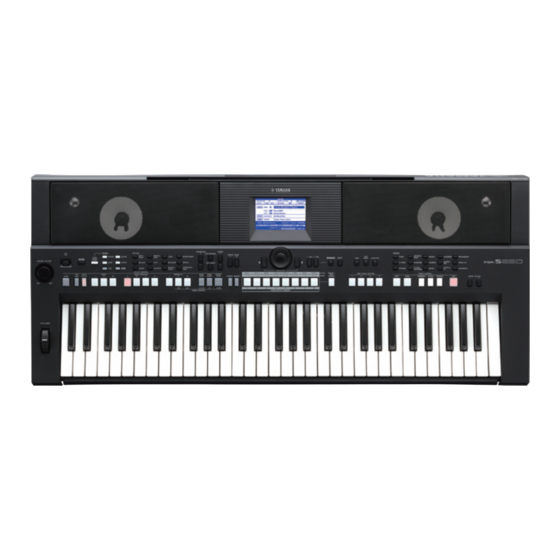
Yamaha PSR-S650 Service Manual
Hide thumbs
Also See for PSR-S650:
- Owner's manual (77 pages) ,
- Reference manual (53 pages) ,
- Manual (29 pages)
Advertisement
Products names are as follows.
(商品名は以下のようになります。)
For Japanese market(国内向け):
DIGITAL KEYBOARD
For overseas market(海外向け):
DIGITAL WORKSTATION
PK
001865
20111101-78750
SERVICE MANUAL
SPECIFICATIONS(総合仕様) ........................................ 3/5
BLOCK DIAGRAM(ブロックダイアグラム) ..................... 7
PANEL LAYOUT(パネルレイアウト) ................................ 8
(ユニットレイアウト & 結線図) ........................................ 10
DISASSEMBLY PROCEDURE(分解手順) ..................... 12
LSI PIN DESCRIPTION(LSI 端子機能表) . ...................... 19
CIRCUIT BOARDS(シート基板図) ................................. 23
TEST PROGRAM(テストプログラム) ....................... 33/37
INITIALIZATION(初期化) ........................................... 41/42
( コンピューターと接続する) ...................................... 43/44
(起動フローチャート) .................................................. 45/46
PARTS LIST
OVERALL CIRCUIT DIAGRAM(総回路図)
Copyright (c) Yamaha Corporation. All rights reserved. PDF
HAMAMATSU, JAPAN
'11.09
&
Advertisement
Chapters

Related Manuals for Yamaha PSR-S650


Summary of Contents for Yamaha PSR-S650
-
Page 1: Table Of Contents
TEST PROGRAM(テストプログラム) ....... 33/37 (商品名は以下のようになります。) INITIALIZATION(初期化) ........... 41/42 CONNECTING A PERSONAL COMPUTER For Japanese market(国内向け): ( コンピューターと接続する) ........43/44 DIGITAL KEYBOARD SYSTEM BOOTING FLOWCHART For overseas market(海外向け): (起動フローチャート) ..........45/46 DIGITAL WORKSTATION PARTS LIST OVERALL CIRCUIT DIAGRAM(総回路図) 001865 HAMAMATSU, JAPAN 20111101-78750 Copyright (c) Yamaha Corporation. All rights reserved. PDF ’11.09 &... - Page 2 IMPORTANT NOTICE This manual has been provided for the use of authorized Yamaha Retailers and their service personnel. It has been assumed that basic service procedures inherent to the industry, and more specifically Yamaha Products, are already known and understood by the users, and have therefore not been restated.
-
Page 3: Contents(目次) Specifications(総合仕様
PSR-S650 SPECIFICATIONS Dimensions W x D x H 946 x 405 x 137 mm (37-1/4" x 15-15/16" x 5-3/8") Size/Weight Weight 7.3Kg (16 lbs. 1 oz.) Number of Keys Keyboard Touch Response Type 320 x 240 dots QVGA B/W 4.3 inch display... - Page 4 Included Accessories • AC Power adaptor (*PA-300 or an equivalent recommended by Yamaha) * May not be included depending on your particular area. • Adaptor: PA-300 or an equivalent recommended by Yamaha • Footswitch: FC4/FC5 Optional Accessories • Keyboard Stand: L-6/L-7...
- Page 5 PSR-S650 総合仕様 寸法 幅×奥行き×高さ 946 × 405 × 137 mm サイズ / 重量 質量 7.3kg 鍵盤数 鍵盤 タッチレスポンス ○ タイプ モノクロ QVGA LCD 4.3 インチ コントラスト ○ ディスプレイ 譜面表示 ○ 歌詞表示 ○ 言語 英語 / 日本語 コントローラー ピッチベンドホイール ○ パネル 言語 英語 音源 音源方式...
- Page 6 PSR-S650 レジストレーションメモリー 8 ボタン× 8 バンク+フリーズ機能 デモ デモ メトロノーム ○ テンポ 5 〜 280 ファンクション トランスポーズ − 12 〜 0 〜+ 12 全体設定 チューニング 415.3 〜 466.2Hz オクターブボタン ○ スケール ○ エクスパンション パック インストール ○ 内蔵メモリー 約 1,130 KB メモリー メモリー / 外付けドライブ...
-
Page 7: Block Diagram(ブロックダイアグラム
PITCH VR601 BEND UNIT CN601 (3P) Expandable up to 512Mbit (512Mbitまで拡張可能) SW & LED Matrix Expandable up to 256Mbit (256Mbitまで拡張可能) CN203 (3P) LD101–121, LED Back EC701 SW101–129, 320x 240 SW131,133,135,137,139, Light SW & LED SW & LED SW141–156 Matrix Matrix CN701 (3P) LD301–307, LD201–213,... -
Page 8: Panel Layout(パネルレイアウト
PSR-S650 PANEL LAYOUT(パネルレイアウト) Flont Panel A’ ■ Front Panel ■ フロントパネル q [ ] (電源 切/入)スイッチ ] (Standby/On) switch w [MASTER VOLUME] control w [全体音量] (MASTER VOLUME)コントロール e [DEMO] button e [デモ] (DEMO)ボタン r [SONG MODE] button r [ソングモード] (SONG MODE)ボタン t SONG buttons t ソングボタン群 y [USB] button y [USB]ボタン... - Page 9 PSR-S650 Rear Panel A’ @1 VOICE category selection buttons @1 楽器(VOICE)ボタン群 @2 VOICE CONTROL buttons @2 ボイスコントロールボタン群 @3 UPPER OCTAVE buttons @3 オクターブ(UPPER OCTAVE)ボタン @4 PITCH BEND wheel @4 ピッチベンドホイール ■ Rear Panel ■ リアパネル @5 CONTRAST knob @5 CONTRASTつまみ @6 [USB TO HOST] terminal @6 [USB TO HOST] 端子...
-
Page 10: Circuit Board Layout & Wiring(ユニットレイアウト & 結線図
PSR-S650 CIRCUIT BOARD LAYOUT & WIRING(ユニットレイアウト & 結線図) SPEAKER (WOOFER) SPEAKER (WOOFER) Lower case assembly (スピーカ (ウーファー) ) (スピーカ (ウーファー) ) (下ケース Ass y) Upper case assembly (上ケース Ass y) SPEAKER (TWEETER) SPEAKER (TWEETER) (スピーカ (ツイーター) ) (スピーカ (ツイーター) )... - Page 11 PSR-S650 LCD UNIT Upper case assembly (液晶ユニット) (上ケース Ass y) Unit Name Location Parts No. Connector Assembly Destination Remarks (ユニット名) (ロケーション) (部品番号) (束線名) (配線先) (備考) WU967500 LCD UNIT LCD UNIT DM-CN2 w -1 TW (Right) AM-CN404 (WW95890) 2P L=520 w -2 TW (Left)
-
Page 12: Disassembly Procedure(分解手順
PSR-S650 DISASSEMBLY PROCEDURE(分解手順) CAUTION: • Be sure to attach the removed fi lament tape just as it was before removal. • Contacts are visible from the back. Pay attention not to insert and install the cable to the connector inversely. (Fig.1) (注意) : Front Side(表面) Back Side(裏面) • 一度剥がしたフィラメントテープは、取り外す前と同じように、 取り付けてください。 • フラットケーブルの接点が裏側から透けて見えます。コネクタ にケーブルの表、裏を逆に差し込まないように注意して取り付 けてください。 (図 1) Lower Case Assembly 1. 下ケースAss y ( 所要時間: 約2分) (Time required: About 2 minutes) 1-1 [80A]の ネ ジ6本、[90]の ネ ジ2本 と[100A]の ネ ジ2 Remove the six (6) screws marked [80A], two (2) 本を外して、下ケースAss yを外します。... - Page 13 PSR-S650 DM Circuit Board 2. DMシート (所要時間: 約3分) (Time required: About 3 minutes) 2-1 下ケースAss yを外します。 ( 1項参照) Remove the lower case assembly. (See procedure 1.) 2-2 [380A]の ネ ジ2本 と[380B]の ネ ジ3本 を 外 し て、 Remove the two (2) screws marked [380A] and three (3) DMシートを外します。...
- Page 14 PSR-S650 ENC Circuit Board 5. ENCシート (所要時間: 約2分) (Time required: About 2 minutes) 5-1 下ケースAss yを外します。 ( 1項参照) Remove the lower case assembly. (See procedure 1) 5-2 コントロールパネル面からエンコーダツマミを外 Remove the encoder knob from the control panel します。 ( 図1、図4) surface. (Fig. 1, Fig. 4) 5-3 ...
- Page 15 PSR-S650 Lower Key Bed Assembly 8. 下ケース鍵盤Ass y ( 所要時間: 約2分) (Time required: About 2 minutes) 8-1 下ケースAss yを外します。 ( 1項参照) Remove the lower case assembly. (See procedure 1) 8-2 [80B] の ネ ジ2本 と、 [ 100B] の ネ ジ1本 を 外 し て、...
- Page 16 PSR-S650 PNR Circuit Board 11. PNRシート (所要時間: 約4分) (Time required: About 4 minutes) 11-1 下ケースAss yを外します。 ( 1項参照) 11-1 Remove the lower case assembly. (See procedure 1) 11-2 下ケース鍵盤Ass yを外します。 ( 8項参照) 11-2 Remove the lower key bed assembly. (See procedure 8.) 11-3 ...
- Page 17 PSR-S650 Disassembling Keyboard Assembly 15. 鍵盤Ass yの分解 (所要時間: 約13分) (Time required: About 13 minutes) 15-1 下ケースAss yを外します。 ( 1項参照) 15-1 Remove the lower case assembly. (See procedure 1.) 15-2 下ケース鍵盤Ass yを外します。 ( 8項参照) 15-2 Remove the lower key bed assembly. (See procedure 8.) 15-3 ...
- Page 18 PSR-S650 Top view (上から見た図) RUBBER CONTACT RUBBER CONTACT (接点ゴム) (接点ゴム) [100C] [100D] RUBBER CONTACT RUBBER CONTACT RUBBER CONTACT (接点ゴム) (接点ゴム) (接点ゴム) [100C] [100C] [100C] [100D] [100D] [110A] [110A] 61H-MK [110B] 61L-MK Fig. 10 ( 図10) 61L-MK 61H-MK Fig. 11 ( 図11)...
-
Page 19: Lsi Pin Description(Lsi 端子機能表
PSR-S650 LSI PIN DESCRIPTION(LSI 端子機能表) AK4385ET (X6040A01) DAC (Digital to Analog Converter) ..............22 R8A02032BG (X8810A00) CPU (SWX02) ...................20 S1D13700F01A100 (X5422A00) LCD CONTROLLER ...............22 µPD789022GB-A15-8E (XZ56010R) CPU ..................19 µPD780031AYGK-N09 (XZ916300) E-PNS2a LED/SWITCH DRIVER ..........19 μPD780031AYGK-N09 (XZ916300) E-PNS2a LED/SWITCH DRIVER PNC: IC101... - Page 20 PSR-S650 R8A02032BG (X8810A00) CPU (SWX02) DM: IC3 OUTER OUTER NAME FUNCTION NAME FUNCTION Ground VSSPLL PLL analog ground ADC analog input 2 Wave memory data bus 6 ADC analog input 1 Wave memory data bus 7 Ground Wave memory data bus 8...
- Page 21 PSR-S650 OUTER OUTER NAME FUNCTION NAME FUNCTION MA15 Wave memory address bus 15 Parallel port A6 MA16 Wave memory address bus 16 Parallel port A7 MA17 Wave memory address bus 17 VCCQ Power supply +3.3 V MA18 Wave memory address bus 18...
- Page 22 PSR-S650 S1D13700F01A100 (X5422A00) LCD CONTROLLER DM: IC7 NAME FUNCTION NAME FUNCTION – Ground – Ground AB12 XCD1 Drain output AB11 XCG1 Gate input AB10 Adorress bus RESET# Reset SCANEN Test mode set up input TESTEN HIOVDD – Power supply CLKI...
-
Page 23: Circuit Boards(シート基板図
PSR-S650 CIRCUIT BOARDS(シート基板図) AM Circuit Board (YD152C0) ....................23 ENC Circuit Board (YD152C0) ....................24 MVR Circuit Board (YD152C0) ....................24 PB Circuit Board (YD152C0) .....................25 TW Circuit Board (YD152C0) ....................25 DM Circuit Board (YD151C0) ....................24/25 PNC Circuit Board (YD154B0) .....................26/27 PNL Circuit Board (YD153C0) ....................28/29 PNR Circuit Board (YD153C0) .....................30/31... -
Page 24: Enc Circuit Board (Yd152C0)
PSR-S650 to 61H-MK-CN1 DM Circuit Board to AM-CN402 to 61L-MK-CN5 to LCD UNIT to LCD UNIT not installed to PNC-CN106 to 61H-MK-CN2 Component side(部品側) ENC Circuit Board MVR Circuit Board MASTER VOLUME to PNL-CN202 to PNC-CN107 Component side(部品側) Component side(部品側)... -
Page 25: Pb Circuit Board (Yd152C0)
PSR-S650 DM Circuit Board Pattern side(パターン側) PB Circuit Board TW Circuit Board to AM-CN404 (Right side) to TWEETER R to PNL-CN203 to AM-CN405 (Left side) to TWEETER L Component side(部品側) Component side(部品側) DM: 2NA-WW38420-1 PB,TW: 2NA-WW38430-1... -
Page 26: Pnc Circuit Board (Yd154B0)
PSR-S650 PNC Circuit Board to PNL-CN204 to AM-CN401 A’ to ENC-CN701 to DM-CN3 to PNR-CN301 A’ Component side(部品側) 2NA-WW38450-1... - Page 27 PSR-S650 PNC Circuit Board B’ B’ Pattern side(パターン側) 2NA-WW38450-1...
-
Page 28: Pnl Circuit Board (Yd153C0)
PSR-S650 PNL Circuit Board to PNC-CN103 C’ to PB-CN601 to MVR-CN501 C’ Component side(部品側) 2NA-WW38440-1... - Page 29 PSR-S650 PNL Circuit Board D’ D’ Pattern side(パターン側) 2NA-WW38440-1...
-
Page 30: Pnr Circuit Board (Yd153C0)
PSR-S650 PNR Circuit Board E’ to PNC-CN102 E’ Component side(部品側) 2NA-WW38440-1... - Page 31 PSR-S650 PNR Circuit Board F’ F’ Pattern side(パターン側) 2NA-WW38440-1...
-
Page 32: Mk Circuit Board (X2335D0)
PSR-S650 61H-MK Circuit Board Scale: 70/100 to DM-CN6 to 61L-MK-CN4 to DM-CN4 G’ G’ Component side(部品側) 61L-MK Circuit Board H’ H’ to DM-CN5 to 61H-MK-CN3 Component side(部品側) 61H-MK: 2NAKB-V869540 61L-MK: 2NAKB-V869520... -
Page 33: Test Program(テストプログラム
PSR-S650 TEST PROGRAM * If the test number 52 “Factory Set” is executed, the data already set will be lost. Preparations 1) Use an AC adaptor PA-300C, PA-300B or PA-301. 2) Measuring device: Frequency counter, which can detect thousandth value or more, Level meter (with JIS-C fi lter), Oscilloscope Note: Use a stereo plug and connect a load resistor of 33 Ω... - Page 34 PSR-S650 TEST No LCD display Test descriptions, judging conditions, etc. Plays each key automatically in the order of scale (auto-scaling). (32 notes from C2 to G4 will be played.) 008 TG1 Chk Make sure that there is no abnormal sounds or noise. When the auto-scaling is fi nished, “TG1 End”...
- Page 35 PSR-S650 TEST No LCD display Test descriptions, judging conditions, etc. Checks the ROM connected to the CPU bus. (Full address) 047 Rom Chk 2 Make sure that “Rom OK” is displayed on the LCD. This test takes a few seconds.
- Page 36 PSR-S650 Switch test item list Turn SW Name LCD Display Note Number Turn SW Name LCD Display Note Number EXECUTE EXECUTE DEMO DEMO EXIT EXIT SONG MODE SONG MODE PRESET SONG PRESET SYNC STOP SYNC STOP SYNC START SYNC START...
- Page 37 PSR-S650 テストプログラム ※テストナンバー 52 の Factory Set を実行すると、設定したデータが失われます。 1 準備 1) AC アダプターは PA-300C、PA-300B または PA-301 を使用します。 2) 測定器 : 周波数カウンター(小数点以下 3 桁以上測定可能なもの) 、レベルメーター (JIS-C フィルター使用 )、オシロ スコープ 注) 特に指示のない限りステレオプラグを用い、 [PHONES/OUTPUT] 端子に 33 Ωの負荷抵抗を接続して測定します。 測定器の入力インピーダンスは 1 M Ω以上であること。 3) 治具 : フットスイッチ(FC-4 または FC-5) 、USB ケーブル、USB ストレージデバイス...
- Page 38 PSR-S650 テスト No LCD 表示 テスト内容及び判定条件など 008 TG1 Chk 鍵盤を自動的にスケーリングします。 (発音鍵域は、C2 から G4 までの 32 音です。 ) 異音、ノイズの無いことを確認します。オートスケーリングが終了すると、 TG1 End と表示されます。この項目では、鍵盤を弾くことで発音します。 (単音、先着優先) 009 Pit Chk ピッチ精度のチェック。 [PHONES/OUTPUT] 端子に周波数カウンターを接続します。 (L か R のどちらか) 正しい信号が出力されていることを確認します。 (441.0 Hz ± 0.2 Hz) ボリューム減衰値 [PHONES/OUTPUT] 端子の L, R にレベルメーター (JIS-C フィルター使用) を接続します。...
- Page 39 PSR-S650 テスト No LCD 表示 テスト内容及び判定条件など 047 Rom Chk 2 CPU のバスに接続されている ROM をチェックします。 (フルアドレス) LCD に Rom OK が表示されることを確認します。 このテスト項目は数秒かかります。 048 Ram Chk2 CPU のバスに接続されている RAM をチェックします。 (フルアドレス) LCD に Ram OK が表示されることを確認します。 このテスト項目は 1 秒で終了します。 049 Flash Rom Chk2 CPU のバスに接続されている Flash ROM をチェックします。 (フルアドレス)...
- Page 40 PSR-S650 SW テスト項目リスト 順番 SW 名 ディスプレイ表示 ノート番号 順番 SW 名 ディスプレイ表示 ノート番号 EXECUTE EXECUTE DEMO DEMO EXIT EXIT SONG MODE SONG MODE PRESET SONG PRESET SYNC STOP SYNC STOP SYNC START SYNC START SCORE SONG SCORE START/STOP START/STOP USER...
-
Page 41: Initialization(初期化
PSR-S650 INITIALIZATION This function erases Backup data or Memory data independently and restores the initial default settings. The following initialization procedures are provided. Expansion contents transferred to internal fl ash memory by installing the expansion pack cannot be deleted by this function. - Page 42 PSR-S650 初期化 バックアップデータとメモリーデータを個別に初期化する(工場出荷時の状態に戻す)ことができます。ただしエクスパン ションパックのインストールで内部メモリーに入ったボイスやスタイルは初期化されません。 ● バックアップデータを初期化する 鍵盤の最高音(白鍵)を押しながら[ ] (電源 切 / 入)スイッチを押して電源を入れます。 ● メモリーデータを初期化する 鍵盤の最高音(白鍵)と一番高い黒鍵 3 つを同時に押しながら[ ] (電源 切 / 入)スイッチを押して電源を入れます。 メモリーデータを初期化すると、購入した有料のデータも消去されます。消去したくないデータは、必 要に応じて USB フラッシュメモリーやコンピューターに保存します。...
-
Page 43: Connecting A Personal Computer (
When data communication is unstable or some problem occurs even though you’ve executed the above instructions, download the Yamaha Standard USBMIDI driver from the following URL then install it to your computer. For instructions on installation, refer to the Install Guide included in the package fi le. - Page 44 PSR-S650 コンピューターと接続する 対応 OS: W indows XP Professional (SP3) / XP Home Edition (SP3) 、Windows Vista、Windows 7、 Mac OS X Version 10.5.0 〜 10.6.x 楽器の電源を切り、コンピューターを起動させます。 コンピューター上のアプリケーションは、すべて終了しておきます。 楽器とコンピューターを USB ケーブルで接続します。 USB 端子 [USB TO HOST] 端子 コンピューター USBケーブル PSR-S650 楽器の電源を入れます。 通常はこの状態で通信できますが、動作が不安定だったり不具合が発生したりする場合は、ヤマハ標準の USB-MIDI ドライバーを下記の URL からインストールして使用します。インストール方法は、ダウンロードファイルに付属さ れているインストールガイドを参照してください。 ...
-
Page 45: System Booting Flowchart (
PSR-S650 SYSTEM BOOTING FLOWCHART Power On Meaning of marks Description of NG judgment Normal Process Judgment EICN = L (IC3, D12) Description of Access to IC8 starts TxD0 = H (IC3, B7) Indication operation TxD1 = H (IC3, B6) Clock output from SYSCLK... - Page 46 PSR-S650 起動フローチャート Power On 解説 NG 判定解説 通常処理 判断 EICN = L (IC3, D12) 動作解説 IC8へのアクセスが始まる 表示 TxD0 = H (IC3, B7) TxD1 = H (IC3, B6) SYSCLK(IC3, Y12)から CPU各種レジスタ設定 クロック出力が始まる MKS ACK送信 TXD1 = L (IC3, B6) TXD1 = H (IC3, B6) IC5へのアクセスが始まる SDRAM初期化 RXD1, SCK1, TXD1を使用して通信 が始まる EBUSドライバ初期化 SWXポート初期化 (EBUS Start) /MKS-IC = L (IC3, W8) EICN = H (IC3, D12) /WP-WAVEn = L (IC3, P3) /WP-PRGn = L (IC3, P2) ここまで来ない場合疑わしいのは /WP-BKUPn = L (IC3, P1) ・PROGRAM ROM (IC8) の不良 PSWO = H (IC3, N4) ・SDRAM (IC5) の不良...
- Page 47 PARTS LIST CONTENTS(目次) OVERALL ASSEMBLY(総組立) ........2 UPPER CASE ASSEMBLY(上ケ−ス Ass'y) ....4 LOWER CASE ASSEMBLY(下ケース Ass'y) ....6 KEYBOARD ASSEMBLY(16N-C61-2M) ......8 ELECTRICAL PARTS(電気部品) ......9–19 Notes : DESTINATION ABBREVIATIONS A : Australian model M : South African model B : British model O : Chinese model C : Canadian model...
- Page 48 PSR-S650 OVERALL ASSEMBLY (総組立) Music Rest (譜面板) LOWER CASE ASSEMBLY See page 6. (下ケース Ass'y) (6 ページ参照) UPPER CASE ASSEMBLY See page 4. (上ケース Ass'y) (4 ページ参照) LOWER KEY BED ASSEMBLY (下ケース鍵盤 Ass'y) KEYBOARD ASSEMBLY See page 8. (16N-C61 鍵盤 ) (8 ページ参照)...
- Page 49 PART NO. DESCRIPTION 部 品 名 REMARKS REF NO. RANK OVERALL ASSEMBLY 総 組 立 PSR-S650 OVERALL ASSEMBLY 総 組 立 (WW39340) UPPER CASE ASSEMBLY 上 ケ ー ス A s s y (WW39350) LOWER KEY BED ASSEMBLY 下 ケ ー ス 鍵 盤 A s s...
- Page 50 PSR-S650 UPPER CASE ASSEMBLY (上ケ−ス Ass'y) 580 WH501 WH601 310a 310b WH701 <Bottom view>...
- Page 51 名 REMARKS REF NO. RANK UPPER CASE ASSEMBLY 上 ケ ー ス A s s y PSR-S650 UPPER CASE ASSEMBLY 上 ケ ー ス A s s y (WW39350) WW394000 UPPER CASE FINISHED 上 ケ ー ス 塗 装 印 刷 品...
- Page 52 PSR-S650 LOWER CASE ASSEMBLY (下ケース Ass'y) L20b L30b L20a L30a...
- Page 53 名 REMARKS REF NO. RANK LOWER CASE ASSEMBLY 下 ケ ー ス A s s y PSR-S650 LOWER CASE ASSEMBLY 下 ケ ー ス A s s y (WW39360) WW396600 LOWER CASE SUB ASSEMBLY 下 ケ ー ス サ ブ A s s...
- Page 54 名 REMARKS REF NO. QTY RANK KEYBOARD ASSEMBLY 1 6 N − C 6 1 − 2 M PSR-S650 KEYBOARD ASSEMBLY 16N C61 P2M (WE12670) 1 6 N − C 6 1 − 2 M V 3 4 1 2 6 0 0 WHITE KEYS CEGB 白...
- Page 55 PSR-S650 ELECTRICAL PARTS (電気部品) AM/ENC/MVR/PB/TW PART NO. DESCRIPTION 部 品 名 REMARKS REF NO. RANK ELECTRICAL PARTS 電 気 部 品 PSR-S650 WW384600 CIRCUIT BOARD A M シ ー ト (WW38430)(YD152C0) WW384900 CIRCUIT BOARD E N C シ ー ト...
- Page 56 PSR-S650 AM/ENC/MVR/PB/TW PART NO. DESCRIPTION 部 品 名 REMARKS REF NO. RANK C409 V350850R ELECTROLYTIC CAPACITOR 100.00 16.0V TP ケ ミ コ ン C410 VC69480R SEMICONDUCTOR CERAMIC CAP. 0.1000 25V Z TATET 半 導 体 セ ラ コ ン C410 VM902400 SEMICONDUCTOR CERAMIC CAP.
- Page 57 PSR-S650 AM/ENC/MVR/PB/TW and DM PART NO. DESCRIPTION 部 品 名 REMARKS REF NO. RANK R423 HF454100 CARBON RESISTOR 10.0 1/4 J AX TP カ ー ボ ン 抵 抗 R424 HF454100 CARBON RESISTOR 10.0 1/4 J AX TP カ ー...
- Page 58 PSR-S650 PART NO. DESCRIPTION 部 品 名 REMARKS REF NO. RANK C142 US625100 CERAMIC CAPACITOR (CHIP) 0.100 10V K RECT. チ ッ プ セ ラ( B J ) C143 WG888300 MONOLITHIC CERAMIC CAP(CHIP) 10.0 6.3V K TP チ ッ プ 積 層 セ ラ コ ン...
- Page 59 PSR-S650 PART NO. PART NO. DESCRIPTION DESCRIPTION 部 部 品 品 名 名 REMARKS REMARKS REF NO. REF NO. RANK RANK C235 UF03810R ELECTROLYTIC CAPACITOR(CHIP) 100 16V チ ッ プ ケ ミ コ ン C236 US663100 CERAMIC CAPACITOR (CHIP) 1000P 50V K RECT.
- Page 60 PSR-S650 PART NO. DESCRIPTION 部 品 名 REMARKS REF NO. RANK RD457100 CARBON RESISTOR (CHIP) 10.0K 63M J RECT. チ ッ プ 抵 抗 RD45000R CARBON RESISTOR (CHIP) 0.00 63M J RECT. チ ッ プ 抵 抗 RD454470 CARBON RESISTOR (CHIP) 47.0 63M J RECT.
- Page 61 PSR-S650 PART NO. DESCRIPTION 部 品 名 REMARKS REF NO. RANK -115 RD457220 CARBON RESISTOR (CHIP) 22.0K 63M J RECT. チ ッ プ 抵 抗 R116 RD455100 CARBON RESISTOR (CHIP) 100.0 63M J RECT. チ ッ プ 抵 抗 R117 RD455100 CARBON RESISTOR (CHIP) 100.0 63M J RECT.
- Page 62 PSR-S650 DM and PNC PART NO. DESCRIPTION 部 品 名 REMARKS REF NO. RANK R214 RD455100 CARBON RESISTOR (CHIP) 100.0 63M J RECT. チ ッ プ 抵 抗 R300 RD454470 CARBON RESISTOR (CHIP) 47.0 63M J RECT. チ ッ プ...
- Page 63 PSR-S650 PNC and PNL/PNR PART NO. DESCRIPTION 部 品 名 REMARKS REF NO. RANK L101 WM459400 INDUCTOR (CHIP) BLM18PG121SN1D 160 チ ッ プ イ ン ダ ク タ * LD101 WW948900 LED (CHIP) ORANGE SML-D12D8WT86(R/S) チ ッ プ L E...
- Page 64 PSR-S650 PNL/PNR and 61H-MK and 61L-MK PART NO. DESCRIPTION 部 品 名 REMARKS REF NO. RANK CN202 CONNECTOR 2.0A 5P TE ワ イ ヤ ー ト ラ ッ プ (WW11600) CN203 VK024700 CONNECTOR 52147 3P TE ワ イ ヤ ー ト ラ ッ プ...
- Page 65 PSR-S650 61L-MK PART NO. DESCRIPTION 部 品 名 REMARKS REF NO. RANK CN05 VK025100 CONNECTOR 52147 7P TE ワ イ ヤ ー ト ラ ッ プ D001 VB941200 DIODE 1SS133,1SS176 TE-5 ダ イ オ ー ド -072 VB941200 DIODE 1SS133,1SS176 TE-5 ダ...
- Page 66 <Page 1> to LED Back Light PSR-S650 PSR-S650 OVERALL CIRCUIT DIAGRAM 1/5 (DM 1/2) CONTRAST <Page 2 J:7> CONTENTS(索引) AM ......3 DM 1/2 ......1 DM 2/2 ......2 ENC ......3 MVR ......3 PB .......3 PNC ......4 PNL ......5 WARNING PNR ......5...
- Page 67 <Page 2> to PNC-CN106 PSR-S650 PSR-S650 OVERALL CIRCUIT DIAGRAM 2/5 (DM 2/2) <Page 4 B:4> USB HIGH-SIDE POWER SWITCH to 61H-MK-CN2 to 61L-MK-CN5 to 61H-MK-CN1 <Page 3 F:7> <Page 3 F:8> <Page 3 F:6> TO DEVICE <Page 1 C:6> <Page 1 C:7>...
- Page 68 <Page 3> PSR-S650 PSR-S650 OVERALL CIRCUIT DIAGRAM 3/5 (AM, ENC, MVR, PB, TW, 61H-MK, 61L-MK) SPEAKER R TWEETER 28CC1-2001078886-1 1 POWER AMP 13.5W SPEAKER L TWEETER 28CC1-2001078886-1 1 SPEAKER R to PNC-CN104 Black WOOFER <Page 4 G:1> SPEAKER L White...
- Page 69 <Page 4> PSR-S650 PSR-S650 OVERALL CIRCUIT DIAGRAM 4/5 (PNC) to AM-CN401 <Page 3 B:2> to PNR-CN301 to PNL-CN204 <Page 5 H:4> <Page 5 C:2> to ENC-CN701 <Page 3 K:3> E-PNS2a LED/ SWITCH DRIVER to DM-CN3 <Page 2 E:2> DL[6] DL[7]...
- Page 70 <Page 5> PSR-S650 PSR-S650 OVERALL CIRCUIT DIAGRAM 5/5 (PNL, PNR) to PNC-CN103 to MVR-CN501 <Page 4 E:1> <Page 3 K:4> to PB-CN601 OP AMP <Page 3 K:5> OP AMP SONG MAIN MAIN MAIN MAIN MODE VARIATION A VARIATION B VARIATION C...
Need help?
Do you have a question about the PSR-S650 and is the answer not in the manual?
Questions and answers
Hola. Tengo un s-650 que prende y al minuto se pone la pantalla azul, sin caracteres y los botones de funciones se apagan y no responden, se va el audio y no apaga, toca descontar el adaptador de corriente. De ahí no funciona más, lo prendo y solo sale la pantalla azul sin caracteres.. Agradezco su ayuda.
A Yamaha PSR-S650 keyboard displaying a blue screen with no characters and unresponsive buttons after one minute of use could be caused by a system malfunction, corrupted memory data, or a power-related issue. Possible causes include:
1. Corrupted Memory Data – If the internal memory contains corrupted data, it may cause the system to freeze. Performing a memory reset by holding the highest white key and the three highest black keys while turning on the keyboard may resolve this issue.
2. Firmware or Software Issue – If the keyboard’s firmware is malfunctioning or outdated, it may cause display and functionality problems. Updating or reinstalling the firmware, if available, could help.
3. Power Supply Problems – A faulty power adapter or unstable power source may cause the keyboard to crash. Checking the power adapter and using a stable power source can help eliminate this issue.
4. Hardware Failure – A damaged internal component, such as the LCD controller or a faulty circuit, could cause the display to malfunction. In this case, professional servicing may be required.
Performing a memory reset and checking the power supply are the first troubleshooting steps. If the problem persists, servicing may be necessary.
This answer is automatically generated