Table of Contents
Advertisement
Quick Links
Advertisement
Table of Contents

Related Manuals for SteppIR SDA 2000 OptimizIR

Summary of Contents for SteppIR SDA 2000 OptimizIR
-
Page 2: Table Of Contents
Table of Contents Introduction (John Mertel WA7IR) ..................5 Warning ..........................7 Purpose ..........................7 Release History ........................7 Initial Controller Checkout ....................8 Theory ..........................8 Operate Mode ........................9 Power-On Screen ......................9 Modes of Operation ......................10 NORM Mode ........................ - Page 3 Text Color ........................28 Button Text Color ......................28 Button Panel Color ......................28 Button Top Color ......................28 Button Bottom Color ...................... 28 Bottom Select Color ....................... 28 Custom Color 80 ......................28 LCD Default ........................28 Flash File Menu ......................... 29 Read Antenna File ......................
- Page 4 Table of Illustrations Initial Power-On Screen....................... 9 Menu Screen ........................9 Screen After First-Time Power-On ..................11 OptimizIR Front Panel ....................... 12 Setup Main Menu ......................14 Transceiver Interface to Radio................... 19 Transceiver Interface with Y-cable ..................20 Controllers Stacked with Y-cable ..................21 Transceiver Interface to PC only ..................
-
Page 5: Introduction (John Mertel Wa7Ir)
SteppIR controller. We have created this instruction manual to address the needs of both users. The OptimizIR provides a new way to interact with the SteppIR antenna. We have spent significant time developing this product, and have had extensive feedback from customers on the design. - Page 6 The SDA 2000 OptimizIR controller hosts a number of new features – color screen, large display and simplified user interface are what you will first notice when turning on the controller.
-
Page 7: Warning
We highly recommend grounding controller chassis to station ground. An 8-32 ground stud is provided for this purpose. SteppIR recommends a short length of at least ¼” wide tin-copper braid. -
Page 8: Initial Controller Checkout
4. Turn on controller by pressing POWER button. 5. Power/Tuning LED should now glow green. 6. NORM LED should glow green. 7. Verify screen shows “SteppIR” logo for about 6 seconds and then shows the startup screen similar to front page shown in this manual. Theory Yagi antennas are basically single frequency devices that work well only over a very narrow range, typically 0.5% change in frequency. -
Page 9: Operate Mode
Operate Mode Power-On Screen When controller is first powered on, the SteppIR logo, controller model and copyright information are displayed for about 6 seconds, and then controller enters operate state. Initial Power-On Screen The check fault enunciator will display if no control cable is connected or if controller detects an error. -
Page 10: Modes Of Operation
180 Mode The 180 degree mode is one of the most popular among SteppIR users. The 180 mode allows the user to electrically “rotate” antenna 180 degrees from the current NORM direction beam heading. This is done by simply pressing a button. In 2-1/2 seconds, (shorter on higher frequencies, longer on lower frequencies) transformation is complete. -
Page 11: Screen After First-Time Power-On
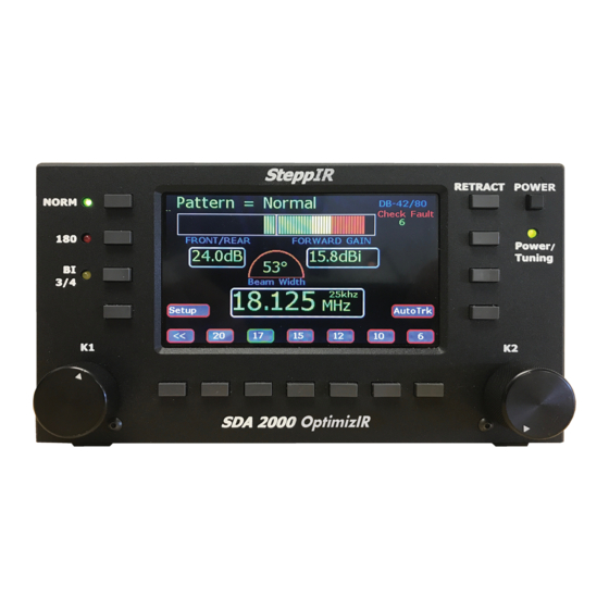
Selected patterns Front to Back, Forward Gain and Beam Width Frequency setting Fault message if there is a problem needing attention. Pattern = Normal DB-18E Front to back Forward gain 0.0dB 0.0dBi Screen After First-Time Power-On There are pushbuttons surrounding the TFT full-color display. The buttons are labeled NORM, 180 and BI 3/4. -
Page 12: Optimizir Buttons In Operate Mode
During antenna length changes, both affected band button and Power/Tuning LED located below POWER button will blink at one second intervals. When tuning is done, band button will have a steady green border. OptimizIR Buttons in Operate Mode OptimizIR Front Panel The NORM button selects the Forward antenna patterns used in conjunction with the K1 knob. -
Page 13: Setup Mode
SteppIR antenna EDU. With SteppIR antennas, it is ALWAYS good practice at any power level to wait for tuning to stop before transmitting. -
Page 14: Options Menu
SETUP Menu K1 for next item Options Menu Setup Main Menu The Setup Menu comprises sub-menus some of which are optional depending on antenna type. Scroll through list of menu items with K1 or K2 knobs. The list does not loop. The items will change rapidly so turn knob slowly. -
Page 15: Remote Driver Option
This option does not enable 6 meter band. It is used to tell controller that antenna has optional 6 meter passive element. If 6 meter Passive Element Kit is installed on antenna, select “Yes” with K2 knob and press Select button. The lengths for the 6m passive element will be active for the NORM and 180 positions in the frequency range of 50 through 51 MHz. -
Page 16: Calibrate Antenna
a negative correction factor (making elements shorter) until SWR is low will allow antenna to operate normally. When water, snow or ice is gone, put antenna correction back to original setting. This feature allows the user to use antenna in any weather conditions with no performance degradation, as opposed to fixed element length Yagi’s which may be unusable for as long as elements have water, snow or ice on them. -
Page 17: Autotrack Settings
If optional “Power Off Retract” is selected, controller will go to sleep when retraction is done. Before taking a SteppIR antenna down, always first RETRACT elements. To protect antenna and connected equipment during periods of non-use, lightning storms or harsh winter conditions, use RETRACT feature. -
Page 18: Band Limit Settings
It also allows the user to connect the SteppIR directly to a PC. An optional “Y” cable is available from SteppIR that allows the user to run a logging program concurrently with the SteppIR controller. -
Page 19: Transceiver Interface To Radio
More than one radio may work for a given radio setting. For example, the Kenwood setting works for Elecraft and the FT9000 setting works for the FT3000 and FT6000. If radio model is not listed, check transceiver interface manual. Finally, some radios require settings to be changed to get their CAT port to work. -
Page 20: Transceiver Interface With Y-Cable
Y-cable is used to link controller and radio to a PC. Used with logging programs. Controller Data In/ Radio Data Radio Data Station ground Computer Data In Transceiver Interface with Y-cable... -
Page 21: Controllers Stacked With Y-Cable
Data Controller Data In/ Radio Station ground Shown below are two steppIR controllers stacked using a cable. Also being used is the Y cable to link both controllers to the radio and PC Computer Data In Controllers Stacked with Y-cable... -
Page 22: Transceiver Interface To Pc Only
Controller Data In/ Radio Data Station ground Computer Data In This configuration shows the controller linked to the PC with a cable. This can be done if station has many different radios linked to PC. This will allow user to control everything from the PC Transceiver Interface to PC only... -
Page 23: Motors Test
The purpose is to verify the elements are wired correctly and correct element is moving. Also, some SteppIR antennas have assembly tests that require probing element for a continuity test. If element makes a chattering noise and doesn’t move, but then after a few seconds... -
Page 24: Relays Test
Select the SETUP button, and turn K2 knob to select “Motors Test”. Press SELECT and the controller will automatically send any of the elements home before doing any of the test. This will be shown by the amber/green light flashing. Use the “Element” button to select individual elements or all of the elements for the antenna. -
Page 25: Reset User Data
(any master segment where a ham band occurs) SteppIR modeled the master antenna at a frequency near the center of each ham band. So if the user is changing a model and creates the new antenna near the center of the frequency range, that antenna will then be replicated throughout the entire segment. - Page 26 The factory default antennas programmed into the controller have been modeled and field tested to provide very good gain, without sacrificing front-to-rear performance. The Create/Modify menu allows the user to change the length of any SteppIR elements for each master antenna segment. This feature can be used to try out custom antenna designs, or to “tune out”...
-
Page 27: Select Pattern
The frequency coverage range of each of the antennas is broken up into numerous blocks for each direction (NORM, 180, and BI 3/4). Each covered by a different antenna model. Using the “Create/Modify” mode, the user can modify and save any of the master antennas in each of these frequency ranges. -
Page 28: Lcd Display Setup
The Clear, Copy, Save and Exit buttons are active for 1) Select Pattern, 2) Adjust Element, 3) Adjust Frequency, 4) Select Segment and 5) Band Correction settings. Clear: Press this to remove currently selected pattern from this band. This will not clear Normal or 180. Copy: This will make a new pattern copied from currently selected pattern. -
Page 29: Flash File Menu
Flash File menu. The file can be saved as an antenna file or as the stepper supplied file that contains all versions of antenna manufactured by SteppIR. Saved Antenna File A file that was created when using the Save User Antenna File menu. -
Page 30: Updated Master File Available
Here are a couple of possible reasons to use compact flash card: Updated Master File Available The procedure is: 1. Insert compact flash card into controller 2. Go to Flash File Menu 3. Select Read Antenna File 4. Select new Master Antenna File 5. -
Page 31: How To Update Firmware
To update firmware, obtain the following items: 1. USB Type A cable to USB Type B Mini cable (Amazon B00NH11N5A) 2. OptimizIR update programmer (available from SteppIR) The firmware can be updated using the PC via a standard USB connection. The programmer and firmware are provided as a zip file entitled “OptimizIR programmer.zip”. -
Page 32: Tuning Relay
Tuning Relay To prevent application of unintended, excessive RF power while the SteppIR antenna is tuning, the OptimizIR controller provides an isolated pair of contacts from a 3.5 mm stereo jack to interrupt the PTT relay signal to a linear amplifier. The cable is not provided, but a standard 3.5 mm stereo plug to two RCA plug cable sold for audio applications works well... -
Page 33: Remote Driver Board Wiring
mounting plate for mounting the driver board in dry location out by the tower. This will also act as a grounding plate and should be connected to a good ground. Station ground Controller Data In/ Radio Data RJ-45 CAT 5 cable Antenna (provided) control... -
Page 34: Advanced Lightning Protection (Alp)
However, the added circuitry greatly reduces the probability of damaging a driver chip. Driver Chip Replacement If a driver chip fails, they are readily available from SteppIR at www.steppir.com. Memory Card Operations Location of memory card and illustration showing removal and installation of memory card is shown below. -
Page 35: Front View Of Optimizir
Front View of OptimizIR Data Out Data In/Radio connector for for Transceiver Ground stacking antennas Interface stud Tuning relay option 3.5 mm stereo plug Remote RJ45 for remote driver board 25-pin D-sub Power input option Connector connector Connector Rear View of OptimizIR... -
Page 36: Customer Support
For troubleshooting tips you can visit our website at www.steppir.com Links to troubleshooting: Support overview: https://www.steppir.com/support/ Frequently asked questions: https://www.steppir.com/support/faq-frequently-asked-questions/ Troubleshooting tips: https://www.steppir.com/support/troubleshooting-tips/ Manuals and Brochures: https://www.steppir.com/support/manuals/ Expanded troubleshooting: https://www.steppir.com/support/expanded-troubleshooting-guides/ RMA Repair form: https://www.steppir.com/support/return-repair-form/ SteppIR IO Group (replaces the Yahoo group) https://groups.io/g/steppir...
Need help?
Do you have a question about the SDA 2000 OptimizIR and is the answer not in the manual?
Questions and answers