
Related Manuals for LiveU LU600

Summary of Contents for LiveU LU600
- Page 1 LiveU LU600 User Guide Version: 7.5.x May, 2019 Doc Version: 7.5.3 P/N: DOC00211...
-
Page 2: About This Guide
About This Guide LiveU LU600 User Guide About This Guide This user guide describes the LiveU LU600 live video uplink system and provides basic information for the operation of the unit in the field. Advanced operations intended for technical personnel and system NOTES administrators are outside of the scope of this user guide. -
Page 3: Intended Audience
More details on these features appear in the relevant sections inside this manual. Intended Audience This user guide is intended to be used by operators of LiveU’s LU600 Live Video Uplink unit. We assume that operators have basic computer knowledge and are familiar with any video equipment being used (cameras, microphones and so on) and the networking infrastructure to which these LU600 units are connected. -
Page 4: Table Of Contents
Table of Contents LiveU LU600 User Guide Table of Contents Chapter 1: Introducing the LU600 ..................12 Overview ............................ 12 What’s in the LU600 Box? ......................13 Hardware Configurations ......................14 Video Interface Cards ..................... 14 Camera-Mount Configurations ..................15 External Antenna Enclosure.................... - Page 5 Introducing Store & Forward ....................50 Live & Store ..........................50 Setting Up the Camera ......................51 Configuring S&F on the LU600 Unit ..................51 Setting the File Prefix ......................51 Selecting Local Storage ....................52 Configuring an S&F Session ..................... 52 Starting the S&F Session ......................
- Page 6 What is the next step after inserting the SIM cards into the LU600 unit? ....94 How do I know whether or not the LU600 unit is connected to the Internet? ..95 The LU600 unit does not connect to the Internet. What is the problem? ....95 What is the purpose of the micro SD slot? ..............
- Page 7 Table of Figures LiveU LU600 User Guide Appendix A: Safety and Maintenance ................98 Safety Information ........................98 Potential Hazards ........................99 Appendix B: Limitation of Liability and Warranty ............. 101 Limitation of Liability and Warranty ..................101 Appendix C: Regulatory Compliance ................102...
- Page 8 Figure 4: Unit Under Remote Control ..........................17 Figure 5: LiveU LU600 Home Screen ..........................19 Figure 6: Camera Not Connected message ........................ 20 Figure 7: LiveU LU600 Battery Status Screen ........................21 Figure 8: IFB Volume Screen ............................. 21 Figure 9: DC IN Connector ............................... 23 Figure 10: Power Switch ..............................
- Page 9 Figure 90: LU600 Remote Control – Unit is Turned Off ....................77 Figure 91: LU600 Wired Remote Control ......................... 78 Figure 92: LU600 is Turned On, But Not Ready to Stream ..................... 78 Figure 93: LU600 is Turned On and is Ready to Stream ....................79 Figure 94: LU600 is Streaming............................
- Page 10 Table of Figures LiveU LU600 User Guide Figure 102: LU600 Battery ..............................86 Figure 103: Releasing the Battery ............................ 87 Figure 104: Ethernet Connections ........................... 88 Figure 105: Unzipping the Bottom Compartment ......................89 Figure 106: Expanding the Bottom Compartment ....................... 89 Figure 107: Unzipping the Compartment’s Zipper ......................
- Page 11 International Phone Line: 1-(609)-997-0600 When contacting a support representative, please make sure to have the last five digits of the LU600’s serial number available. This can be found by selecting the About option, as described in the About section on page 49.
-
Page 12: Chapter 1: Introducing The Lu600
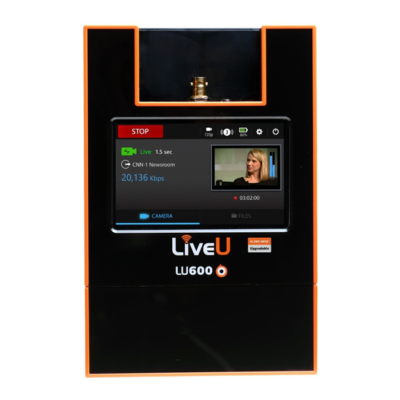
ON/OFF Figure 1: LU600 As the LU600 powers up, it dials (connects) its modems, connects the WiFi / Ethernet interfaces to various networks and combines their bandwidth into a single consolidated broadband uplink connection. The LU600 can then encode incoming video into an H.264 (or HEVC) stream and transmit it over the aggregated bandwidth or use this bandwidth for DataBridge functionality. -
Page 13: What's In The Lu600 Box
The LU2000 server runs multiple Multi-Media Hub (MMH) instances, where each MMH recombines the streams received from a specific field unit (e.g. the LU600) into a discrete broadcast-quality video stream that can be played out over an integrated SDI interface on the LU2000 or streamed from the LU2000 to a CDN. -
Page 14: Hardware Configurations
Video Interface Cards The base LU600 comes with the HEVC-HD video interface card that supports HD video input via either SDI or HDMI connectors. This card supports the following video connections: 3G/HD/SD-SDI and HDMI 1.4. -
Page 15: Camera-Mount Configurations
LiveU LU600 User Guide 4K Video Support When the above video cards are used, the LU600 is able to support 4K video in all operational modes, i.e. Live, Live & Store, and Store & Forward. Based on the card used,... -
Page 16: External Antenna Accessory
LiveU LU600 User Guide Figure 6: LU600-SMA External Antenna Accessory As part of the accessories available for the LU600, LiveU offers external cellular antennas (part number ANT0026) that were tested and found to be highly compatible with the LU600. Figure 7: External Cellular Antenna (ANT00026) These antennae have the following advantages: •... -
Page 17: Liveu Central
LiveU LU600 User Guide LiveU Central LiveU Central is a web interface that lets you access any LiveU field unit you have, including the LU600. LiveU Central runs in any modern web browser such as Google Chrome, Internet Explorer or Firefox and allows you to view an LU600’s status and to remotely configure an LU600 and an MMH instance (running on the LU2000 server). -
Page 18: Chapter 2: Quick Start
Quick Start LiveU LU600 User Guide Quick Start This chapter describes how to get started using the LU600 and describes the Home screen and its options. Getting Started The following describes the basic workflow for using the LU600: Power on the LU600 as described in the Powering On the LU600 Unit section on page 22. -
Page 19: Lu600 Home Screen
Quick Start LiveU LU600 User Guide LU600 Home Screen The LU600 user interface is accessed via the LCD touch screen. The Home screen automatically displays when the unit is powered on. All LU600 functionality is accessible directly from the Home screen. -
Page 20: Video Preview And Audio Bars
The video feed is displayed a few seconds after the camera is connected and automatically detected by the LU600. If the LU600 cannot detect any incoming video, this area will display a message “Camera Not Connected”. -
Page 21: Ifb Headphone Detection & Control
LU600. Figure 12: LiveU LU600 Battery Status Screen IFB Headphone Detection & Control A headphone icon will appear whenever a headphone is plugged into the audio jack on the video card. -
Page 22: Chapter 3: Using The Lu600
The LU600 comes with a battery that enables up to four hours of standalone operation when fully charged. If this is the first time that this LU600 is being used, then you may have to attach the battery to the main unit as described in the Attaching and Replacing a Battery section on page 86. -
Page 23: Figure 9: Dc In Connector
To turn on the LU600 unit: Press the Power button for approximately two seconds until the LU600 lights up. The battery does not need to be fully charged to use the unit. The entire boot-up and modem connection process typically takes under 30 seconds. -
Page 24: Connecting The Video Camera
Connect an SDI or HDMI cable to the video-out port on the video camera. Connect the other end of the cable to the appropriate port (SDI or HDMI) on the LU600 unit (when outside the backpack), or to the appropriate cable extender when the LU600 is inside the backpack. -
Page 25: Viewing The Camera Resolution
LiveU LU600 User Guide Figure 18: LU600 Unit Cable Extensions The camera can be connected either before or after turning on the LU600. Please note that only one camera can be connected directly to the LU600 at any time. Viewing the Camera Resolution... -
Page 26: Streaming Operation Mode Selection
The Store & Forward profile is typically used when you are in an area with limited bandwidth as it allows you to store the video on the LU600 unit and to transmit it once bandwidth improves. When this option is selected, the Delay option is not active. -
Page 27: Specifying Store & Forward Streaming Quality
Using the LU600 LiveU LU600 User Guide Figure 21: Selecting Operating Mode - 1 Tap the Live button (as shown above in Figure 21) to display the following screen. Select either Live or Store & Forward video mode. Figure 22: Selecting the Operating Mode Specifying Store &... -
Page 28: Selecting An Output Channel
Selecting an Output Channel You will need to define where your LU600 is going to send its output to. This step is mandatory the first time that you use the LU600, after which the LU600 will use the same... -
Page 29: Figure 18: Selecting A Channel
Using the LU600 LiveU LU600 User Guide To select a channel: Tap the Channel button to display the following screen: Figure 24: Selecting a Channel The channel icons next to the channel name reflects the channel type as follows: •... -
Page 30: Channel Status Display
Figure 26: Channel Busy message Streaming to a Preview Channel (Virtual Group) You might want to have your stream visible in LiveU Central without worrying about exactly which output it’s being routed to. This can be done by streaming to a Virtual Group, which allows LiveU Central operators to preview the channel and then control the destination to which the stream is ultimately directed and sent live. -
Page 31: Marking A Channel As A Favorite
(low bandwidth, at lower resolution and frame rate) preview channel to LiveU Central. Once a LiveU Central operator has allocated a Virtual Channel in Preview mode to a destination (SDI or CDN output), it is streamed at the appropriately defined resolution and frame rate. -
Page 32: Setting Delay
Figure 29: Setting the Delay Use the slider to adjust the delay value. The LU600 will use this value until changed. Here are some guidelines for selecting the delay that best suits your current delay- versus-quality requirements: •... -
Page 33: Handling Network Connections
Tap the Connections button in the Home screen to display the Connections screen which lists the interfaces that the LU600 can connect to. The LU600 will automatically attempt to connect to all its interfaces whenever powered on. Figure 30: Connections Screen... -
Page 34: Cellular Interfaces
Tap an interface in the list to configure it. • Xtender interfaces appear in the Connections screen once an Xtender is connected. You may refer to the LiveU Xtender User Guide for a description of the AP and Client interfaces connected to the Xtender. Cellular Interfaces When tapping on a Cellular connection from the Connections screen, you will be taken to the Cellular Interface screen for that connection / modem. -
Page 35: Figure 26: Apn Configuration Screen
Figure 33: APN Manual Configuration Once you have changed whatever necessary, tap on the Back at the top of the screen, and the LU600 will attempt to reconnect this interface using the new APN information. Manual Network Selection... -
Page 36: Figure 28: Mobile Network Selection Screen
Using the LU600 LiveU LU600 User Guide Figure 34: Mobile Network Selection Screen Tap Scan Networks. The unit will start scanning and display a list of all cellular networks relevant to the SIM installed. This operation may take up to 2 minutes. -
Page 37: Optimized Roaming Pairing (Orp)
When left to their default dialing and connection preference, all of the roaming SIMs in your LU600 will tend to pair to the same operator (either due to signal strength or built-in commercial preference). ORP assures that the modems will pair to the 2, 3 or 4 operators that are available in the specific area / country you’re in. -
Page 38: Figure 32: Connections Settings Screen
Figure 38: Connections Settings Screen • Select the SIM slot that you’d like your LU600 to use for all of the installed Dual- SIM modules (A or B). The system will display the following message Figure 39: Global SIM Slot Switch Message •... -
Page 39: Figure 34: Dual-Sim Cellular Interface Screen
Interface Screen will open. Figure 40: Dual-SIM Cellular Interface Screen • Select the SIM slot that you’d like your LU600 to use for this Dual-SIM module (A or B). The system will display the following message Figure 41: Dual-SIM Slot Switch Message •... -
Page 40: Ethernet Interface Network Parameters
Using the LU600 LiveU LU600 User Guide Ethernet Interface Network Parameters By default, the IP address of an Ethernet interface is obtained automatically from the DHCP server. If preferred, you can manually configure the IP address and other standard network parameters for the Ethernet interface. -
Page 41: Configuring Wifi Network Parameters
LiveU LU600 User Guide Power over Ethernet (PoE) Setting The LU600 can use its Power over Ethernet (PoE) feature to provide power to a WiFi client, such as the UBIQUITI client used with the Xtender. This replaces the need for the WiFi client to be connected to an external power source. -
Page 42: Connecting To A Wifi Network
Connected: The WiFi network is currently connected. Known: The LU600 has previously connected to this network and knows its password. Unknown: The LU600 has not previously connected to this network or does not know its password. • Lock /No Lock : Indicates whether this WiFi network is open or encrypted. -
Page 43: Going Live
NOTE Figure 48: Channel Busy When streaming to a preview channel, you cannot define when the IMPORTANT stream goes live. This can only be performed by a LiveU Central NOTE operator. To stop live transmission: Tap the STOP button (which replaces the START button while the unit is streaming). -
Page 44: Shutting Down
Using the LU600 LiveU LU600 User Guide Shutting Down There are 3 ways to turn off your LU600: Software Tap the Power Down button to display the following screen: Figure 49: Powering Down – 1 NOTE Pressing Restart boots the unit and restarts the LiveU application. -
Page 45: Hardware
Using the LU600 LiveU LU600 User Guide Hardware Hold down the power button for eight seconds to perform a hard shutdown of the unit. Figure 51: Power Button Using the Wired Remote Control To turn off the unit, long press the remote button, as follows: ... -
Page 46: Chapter 4: Advanced Configuration Settings
Advanced Configuration Settings LiveU LU600 User Guide Advanced Configuration Settings This chapter describes how to configure advanced configuration settings on the LU600. Tap the Advanced Configuration button in the Home screen to configure LU600 advanced settings. Figure 52: Settings You can configure the following settings from this screen: •... -
Page 47: Speed Test
Advanced Configuration Settings LiveU LU600 User Guide Speed Test The Speed Test function will allow you to measure the effective connection speed from your unit to the currently chosen output channel. This can be useful when setting up your live session, allowing you to check cellular speeds without connecting a camera. -
Page 48: Store & Forward
4 Channels) and Audio Bitrate (96/128/192/200/320 kbps) used by the unit. The default is 2 channels at 96 kbps. Note that 4 Channel input is only supported when using the SDI connection. Setting the LU600 to 4 channels with an HDMI camera plugged in will only use 2 channels at 96 Kbps. -
Page 49: Auto Resolution
LiveU LU600 User Guide Auto Resolution When Auto Resolution is enabled, the LU600 automatically adjusts the resolution at which it transmits according to the bit rate that is available in order to provide the best available video quality on the server side. This feature is enabled by default and is the recommended mode. -
Page 50: Chapter 5: Store & Forward
SDI interface, chunked (during the file’s forwarding phase), renamed or deleted. The LU600 encodes S&F files at up to 15Mbps video rate, and forwards S&F files at a maximum bitrate of 50Mbps based on available bandwidth. During a S&F session, the unit can store the file on one of two types of destinations: •... -
Page 51: Setting Up The Camera
LiveU LU600 User Guide Setting Up the Camera In order to initiate an S&F session, a camera must be connected to the LU600 unit through the SDI or HDMI inputs of the unit. The camera should be sending video to the LU600 unit (either live, or playing out a previously stored video from the camera’s storage). -
Page 52: Selecting Local Storage
LiveU LU600 User Guide Selecting Local Storage Store & Forward sessions can be stored either on the LU600’s internal storage (12 GB) or on an inserted micro SD card. To select the storage to be used during Store & Forward, tap the dropdown menu and select either the internal storage or the micro SD card. - Page 53 Store & Forward LiveU LU600 User Guide Select the Quality button, shown below: Figure 63: Selecting Quality – 1 The following displays: Figure 64: Selecting Quality – 2 On units with the HEVC Card, you can select either H.264 or HEVC by tapping the relevant button.
-
Page 54: Starting The S&F Session
Store & Forward LiveU LU600 User Guide Starting the S&F Session To start the S&F session: Tap the START button, shown below: Figure 65: Starting the S&F Session The following describes the information displayed describing the S&F session in progress:... -
Page 55: Monitoring S&F Sessions
Store & Forward LiveU LU600 User Guide During S&F streaming, both the Data sent and the Data stored NOTE shown in the progress bar increase, but not necessarily at the same rate. Monitoring S&F Sessions In addition to the Home screen (shown on the previous page), you can monitor the status of your S&F progress by using the Files Transfer Info log. -
Page 56: Monitoring - Files Screen
The Pause/Cancel options are disabled for S&F sessions that are still in progress. Resuming If for any reason the LU600 and the LU2000 are disconnected for under three minutes, then the LU600 will automatically resume forwarding the file once reconnected. - Page 57 LU600. SD Card Displays a list of the files on the LU600’s micro SD card. This option is only active when a micro SD card is inserted in the LU600. Tap one of the storage containers (Internal Storage, SD card and USB drive) to display the list of folders/files that it contains.
-
Page 58: Chapter 6: File Transfer (Ftp)
File Transfer (FTP) LiveU LU600 User Guide File Transfer (FTP) This chapter describes how to use the LU600 to transfer files from the field directly to a Multi-Media Hub running on an LU2000 server. Introduction The LU600 enables you to transfer stored files to an LU2000. This feature can also be used to transfer any other type of file, such as text files, documents and so on. - Page 59 File Transfer (FTP) LiveU LU600 User Guide Figure 71: USB Port Figure 72: LU600 Micro SD Card Slot Tap the button at the bottom of the Home screen. The following screen displays: Figure 73: Storage Selection This screen displays three types of file containers, as follows: Internal Storage Tap this icon to display a list of the files that were being forwarded by the Store &...
- Page 60 USB drive is inserted in the LU600. SD Card Tap this icon to display a list of the files on the LU600’s micro SD card. This option is not active if the LU600 does not have a micro SD card inserted.
- Page 61 File Transfer (FTP) LiveU LU600 User Guide by File You can tap the up/down arrows on the left to sort the list Name, Size or Date , as shown below: NOTE Figure 76: Sorting the File List Tap the Upload button to start sending this file to the LU2000 or the Delete button to delete this file.
-
Page 62: File Upload Indication
File Transfer (FTP) LiveU LU600 User Guide File Upload Indication When a file upload is running in the background (FTP or Store & Forward), the indication displays on the Home screen. This icon shows the overall progress for all file transfers in the queue. -
Page 63: Chapter 7: Interrupted Feedback (Ifb)
Please note that unless you have enabled the “IFB Always On” feature from within LiveU Central, you should make sure that the earphones were physically connected to the unit before starting to stream or the LU600 operator will not be able to hear anything on the IFB channel. -
Page 64: Chapter 8: Video Return
The Video Return feature provides a unidirectional video channel from the Video Return Server (typically situated in the MCR) to LU600 unit operators in the field and is designed to send any video feed required back to the field. This is useful in a number of different live... -
Page 65: Return Channel Selection
Video Return LiveU LU600 User Guide Figure 81: Video Return on the Home Screen You will now be taken to the Video Return Screen where you can select a channel from the Video Return server and START / STOP incoming Video Return. -
Page 66: Video Output
HDMI adapter cable plugged into the mini HDMI-out connector on the top of the unit. Figure 84: Video Return Display You can also display the video full screen on the LU600, by tapping the crosshair icon. To exit full-screen mode, simply double-tap the video. Going live while streaming a Video Return channel Once you have a live Video Return channel displayed on your unit, you can return to the main LU600 screen by tapping the CAMERA button at the bottom left of the screen. -
Page 67: Chapter 9: Databridge Operation
100Mbps. The DataBridge is available as a dedicated hotspot unit based on the LU600 or as part of the LU600 and LU200 video uplink units; enabling users to work with the existing Video and File modes, or with one of the two DataBridge operational modes. -
Page 68: Databridge Mode
The LU600 unit should be switched from Video mode to DataBridge mode in order to operate as a DataBridge. The LU600 will continue to operate in DataBridge mode until it is switched back to Video mode. Switching modes between Video and DataBridge does not... -
Page 69: Operating In Databridge Mode
Figure 86: DataBridge Operating in DataBridge Mode For the LU600 to operate as a DataBridge in Gateway operational mode, the unit must be associated to a DataBridge Gateway instance in LiveU Central. To make sure that the Gateway has been correctly set up, please contact LiveU Support and request that a DataBridge Gateway instance be assigned to the LU600 unit for this purpose. -
Page 70: Databridge Settings
DataBridge Operation LiveU LU600 User Guide Once connected, the DataBridge Home screen will display the current downlink/uplink rate. Pressing the Connections button at the top of the screen opens the Connections screen and shows the specific bitrate used per interface. -
Page 71: Configuring Databridge Wifi Hotspot Parameters
DataBridge Operation LiveU LU600 User Guide Figure 90: DataBridge Operational Mode Screen Configuring DataBridge WiFi Hotspot Parameters To configure DataBridge WiFi Hotspot Parameters, tap the Advanced Configuration button in the Home screen, and select the DataBridge Settings Screen. Now tap on the WiFi Access-point menu item. - Page 72 Toggling Hotspot Station Broadcast Status You can tell the LU600 to open the Hotspot, yet not broadcast its SSID by toggling the ON/OFF switch next to Broadcast. When set to OFF, the WiFi hotspot will be active however any clients that wish to connect to it will need to explicitly configure their WiFi to find and connect.
- Page 73 DataBridge Operation LiveU LU600 User Guide Setting Country Set the country where the LU600 hotspot is being used in order to configure the Hotspot with supported frequencies / channels. Tap on the Country field to select your country from a list.
-
Page 74: Chapter 10: Working With Metadata On The Lu600
This XML file consists of static (locally or remotely edited fields) data, and dynamic (time, location, video format etc.) data. The XML file is sent from the LU600 as part of the session and is saved for later referral and use on the MMH. -
Page 75: Turning Metadata On Or Off
Turning Metadata Prompts On or Off The LU600 can remind you to set Metadata fields whenever you wish to go live or start a Store & Forward session. To set the Metadata Prompt, tap on the “Prompt for Metadata on... -
Page 76: Metadata Field Entry
To clear the current value of any field, tap on the X next to the field. Please note that field values are constantly synchronized with LiveU Central and may be changed by the LiveU Central operator at any time. -
Page 77: Chapter 11: Using The Wired Remote Control
LU600 Wired Remote Control The LU600 backpack includes a wired remote control designed to turn on/off the unit and start/stop live streaming without using the unit’s GUI. This remote also indicates the unit’s status while the unit is being worn by a cameraman. -
Page 78: Connecting The Remote To The Unit
USB memory stick for uploading files. USB Port Figure 97: LU600 Wired Remote Control The wired remote control is designed to work only with the LU600. Plugging it NOTE into other LiveU products or any other device (such as a PC) may cause damage to the device and/or the remote. -
Page 79: Turning Off The Unit
Using the Wired Remote Control LiveU LU600 User Guide Figure 99: LU600 is Turned On and is Ready to Stream Turning Off the Unit To turn off the unit, long press the remote button, as follows: • Software Reset (Recommended): Press and hold the remote button for approximately four seconds. -
Page 80: Stopping Streaming
Using the Wired Remote Control LiveU LU600 User Guide Figure 100: LU600 is Streaming Stopping Streaming Quickly double-press the remote button to stop streaming (this method is designed to prevent sporadic stop-streaming events). Once the unit stops streaming, the Live LED turns... -
Page 81: Chapter 12: Handling The Lu600
Handling the LU600 LiveU LU600 User Guide Handling the LU600 This chapter describes how to perform various tasks for handling the LU600, such as replacing the battery, inserting SIM cards and so on. This chapter contains the following sections: •... - Page 82 To insert module SIM cards: Remove the thumbscrew on the back of the unit. Figure 101: Releasing the Cover Gently pull the cover of the LU600 upwards and off, as shown below: Figure 102: Removing the LU600 Cover to Expose the Modules...
- Page 83 SIM card. The figures below show the correct way to insert the SIM card. Figure 104: Inserting a SIM Card into a Module – 1 Figure 105: Inserting a SIM Card into a Module – 2 Replace the cover of the LU600, remembering to replace and tighten the thumbscrew.
-
Page 84: Dual-Sim Module Installation
Your LU600 unit may have been supplied with Dual-SIM modules. These modules allow you to install 2 sets of SIMs (A and B), where the LU600 GUI provides the option to switch between these SIMs on a specific module or on all modules at once. -
Page 85: Connecting An Extra (9Th) Modem
Handling the LU600 LiveU LU600 User Guide Once the module has been installed in the LU600, the unit will detect the Dual-SIM automatically and you should be able to use the GUI to switch the active SIM slot accordingly as detailed in Dual-SIM Modules – GUI Additions on page 37. -
Page 86: Attaching And Replacing A Battery
Use both hands to press the two battery latch buttons on the left and right sides of the battery. Position the body of the LU600 over the battery by matching the pegs on the unit to the slots on the battery. -
Page 87: To Replace The Battery
Position the body of the LU600 so that it is hovering slightly above the replacement battery. Use both hands to press the two battery latch buttons on the left and right sides of the battery and snap the LU600 body onto the battery. You should hear a click when it is in place. -
Page 88: Ethernet Connection
The LU600 contains a DHCP client. Two Ethernet ports are available. To connect the LU600 to an Ethernet network: • On the back of the LU600, plug in the Ethernet cable into one of the two available Ethernet slots. Figure 110: Ethernet Connections... -
Page 89: Connecting The Lu600 Wifi Client Pouch To The Backpack
Connecting the LU600 WiFi Client Pouch to the Backpack The WiFi Client for the LU600 has one connector – the LAN connector (LAN CBL00218), which connects to the LAN port on the LU600 device. This connector provides both communication and power. - Page 90 Handling the LU600 LiveU LU600 User Guide Unzip the compartment’s zipper to expand the compartment. Figure 113: Unzipping the Compartment’s Zipper Position the pouch so that the cables are on the right, as shown below: Figure 114: Turning the Pouch...
- Page 91 LU600. Figure 116: Pushing the Cable Through the Hole in the Backpack Put the LU600 device into the backpack and connect this cable to its LAN port 2, as shown below:...
- Page 92 Handling the LU600 LiveU LU600 User Guide Figure 117 Connecting the Cable to the LAN Port Close the bottom compartment’s zipper. Open the two Velcro straps on the top of the pouch and the two Velcro straps on the bottom of the pouch.
- Page 93 Handling the LU600 LiveU LU600 User Guide Press the top two Velcro straps down to secure the top part of the pouch to the backpack. Figure 120: Securing the Top Velcro Straps of the Pouch to the Backpack Press the bottom two Velcro straps down to secure the bottom part of the pouch to the backpack.
-
Page 94: Chapter 13: Faqs
(is provided with SIM cards). 2 Where are SIM cards placed? Open the back cover of the LU600 and insert the SIM cards, as described in the Inserting a Module SIM Card section on page 81. 3 How do I know which SIM cards are supported in my country? Browse to the following link to see a list of the operators in your country. -
Page 95: How Do I Know Whether Or Not The Lu600 Unit Is Connected To The Internet
• The SIM cards are not activated or do not support the data plan. • Modems are not plugged in properly into the USB ports inside the LU600 unit. • The APN is not configured correctly on the modems. 7 What is the purpose of the micro SD slot? The micro SD slot can be used for the Store &... -
Page 96: In Which Countries Does The Lu600 Work
Contacting Information section on page 11 for more information. 12 How many hours does the battery last? The LU600 battery lasts for three to four hours depending on the amount of unit activity. 13 Why can I not hear using the earphones/headphones? For the IFB feature to work properly, earphones/headphones must be connected before the streaming starts, or the IFB Always On function should be enabled in LiveU Central. -
Page 97: Can I Stream To Multiple Channels (Lu2000S) At The Same Time
LiveU’s MultiPoint cloud-based IP video distribution service enables video from the field to be streamed from office to office or from an LU600 unit to multiple offices. In the MultiPoint service, video can be streamed from one LU2000 server and distributed to one or more other LU2000 servers. -
Page 98: Appendix A: Safety And Maintenance
LiveU LU600 User Guide Safety and Maintenance This appendix describes how to maintain the LU600 and how to handle potential hazards. Safety Information Do not disassemble this product. Do not remove its cover or its back. There are no user-serviceable parts inside. Refer servicing to qualified service personnel only. -
Page 99: Potential Hazards
To prevent fire or shock hazard, do not expose the product to rain, liquid or moisture. The product can be used in light rain while it is protected by the LU600 backpack and using the attached rain hood. The product is not designed to be used under water. - Page 100 In addition to FAA requirements, many airline regulations state that wireless operations must be suspended before boarding an airplane. Please ensure that the LU600 is turned off prior to boarding aircraft in order to comply with these regulations. The enclosure can transmit signals that could interfere with various onboard systems and controls.
-
Page 101: Appendix B: Limitation Of Liability And Warranty
LiveU product, even if the company has been advised of the possibility of such damages. -
Page 102: Appendix C: Regulatory Compliance
Regulatory Compliance LiveU LU600 User Guide Regulatory Compliance This appendix provides regulatory compliance information including FFC compliance details. Note: This equipment has been tested and found to comply with the limits for a Class B digital device, pursuant to part 15 of the FCC rules. These limits are designed to provide reasonable protection against harmful interference in a residential installation. - Page 103 Regulatory Compliance LiveU LU600 User Guide Standards Compliance ETSI EN 301 489-1 V2.1.1 ETSI EN 301 489-7 V1.3.1 ETSI EN 301 489-17 V3.1.1 Safety IEC/EN 60950-1 A2:2013 CB Scheme Radio EN 300 328 V2.1.1 EN 301893 V2.1.1 EN 301 908-2 V11.1.1 EN 301 908-13 V11.1.1...
- Page 104 REINVENTING LIVE...
Need help?
Do you have a question about the LU600 and is the answer not in the manual?
Questions and answers