
Subscribe to Our Youtube Channel
Related Manuals for Enerpac SBL1100

Summary of Contents for Enerpac SBL1100
- Page 1 Instruction- and Maintenance Manua Super Boom Lift Document Number: ED.03622.00.001.R03.ENG SBL1100 / SBL900 Status: Final Original instructions 1068 / 915 metric ton hydraulic portal lift system www.enerpac.com...
-
Page 2: Lubricants (Kroon Oil
Revisions Approved Description Date Author Checked Th. Westerhof Initial version 23 March 2017 D. Rosier B. Geerdink R. Broenink A. Holterman Added: Transporting frame Index table R. Bosman Document lined up with other Gantry manuals: 9 May 2017 D. Rosier R. -
Page 3: Preface
Preface Dear customer, This is the manual for assembling, using and maintaining of both the SBL1100 and the SBL900 Super Boom Lift systems. In this manual, those machines are referred to by the term “System”. The manual is meant to be used by operators and by maintenance engineers. -
Page 4: Table Of Contents
Contents Preface _______________________________________________________________________ 3 Contents ______________________________________________________________________ 4 Introduction ________________________________________________________________ 7 1.1. Manufacturer address __________________________________________________________ 7 1.2. Declaration ___________________________________________________________________ 7 1.3. Referenced documents __________________________________________________________ 7 1.4. Identification __________________________________________________________________ 7 1.5. Liability ______________________________________________________________________ 8 1.6. Intended use __________________________________________________________________ 8 1.7. Modifications _________________________________________________________________ 8 1.8. - Page 5 4.5. Side load ____________________________________________________________________ 51 Install the System __________________________________________________________ 53 5.1. How to hoist parts of the System _________________________________________________ 53 5.2. Place the Skid Tracks __________________________________________________________ 57 5.3. Put the units upon the skid tracks ________________________________________________ 61 5.4. Connect the power cables ______________________________________________________ 62 5.5.
- Page 6 A. Checklist for planning a lifting operation _______________________________________ 123 B. Checklist for installing the System ____________________________________________ 124 C. Final checks ______________________________________________________________ 126 D. Recording a lifting operation ________________________________________________ 128 Recording maintenance ____________________________________________________ 130 Drawings for the skid tracks _________________________________________________ 133 G.
-
Page 7: Introduction
1. Introduction 1.1. Manufacturer address Enerpac Heavy Lifting Technology B.V Spinelstraat 15, 7554 TS Hengelo The Netherlands Tel. +31 74 242 20 45 Fax. +31 74 243 03 38 Email: info.hengelo@enerpac.com Website: www.enerpac.com 1.2. Declaration Declaration of Conformity according to machine Directive 2006/42/EC. -
Page 8: Liability
This also applies to the installation and adjustment of safety devices and valves and welding work on the System. Spare parts must always meet the technical specifications given by Enerpac in the construction file and the component construction lists for the machine. It is recommended to use original spare parts. -
Page 9: Personnel And Obligations
1.8. Personnel and obligations Only qualified personnel are allowed to operate the System. Qualified personnel are those who have followed the official Gantry training of Enerpac and have obtained the Certificate. Only qualified personnel are allowed to maintain the System. - Page 10 d) verifying that the system has the necessary capacity to perform the proposed operations in the planned configuration. e) ensuring the assigned operators have has been notified of adjustments or repairs that have not yet been completed, prior to commencing operations. f) designating personnel for inspections as required in the applicable chapter.
- Page 11 e) ensuring that personnel involved in the operations understand their responsibilities, assigned duties, and the associated hazards. f) addressing safety concerns raised by the system operator or other personnel and being responsible if he decides to overrule those concerns and directs the operation to continue.
- Page 12 o) knowing and following the procedures specified by the system manufacturer or approved by a qualified person for assembly, disassembly, and setting up the system. p) knowing how to travel the system, if applicable. q) ensuring that the load and rigging weight(s) have been provided. r) calculating or determining the rated load for all configurations that will be used and verifying, using the capacity chart(s), that the system has sufficient capacity for the proposed operation.
-
Page 13: Lifetime
STOP. EMERGENCY STOP. Arm extended, palm down, move Both arms extended, arm back and forth palms down, move horizontally. arms back and forth horizontally. INDIVIDUAL LEGS. EVERYTHING. Hold up: Clasp hands in one finger for leg front of body. marked: "1," two fingers for leg marked "2”. -
Page 14: Warning Symbols Used Within This Document
1.10. Warning symbols used within this document This manual uses warnings and symbols to draw your attention to important safety information. The table below indicate the most common used labels in industrial documents. ‘NB’ is used to highlight important work activities and for additional information Caution 'Caution' is used if failure to heed the given instructions may result... -
Page 15: General Safety Aspects
2. General safety aspects Subjects that must be followed are covered not only in this chapter; also in other chapters are specific safety directions that must be read and followed. 2.1. Mandatory protective gear While using the System ensure that the applicable safety regulations are observed. Make sure that all people on the working place observe the following safety regulations: Always wear •... -
Page 16: General Safety Regulations
Inspect the condition of the System before every individual start-up, given the fact that the slightest defect may have severe consequences. Enerpac is not liable for improper use of accessories in combination with the System. Page 16 of 151 Document number: ED. 03622.00.001.R04.ENG Page 16 ED.02518.00.001.R08.ENG... -
Page 17: Symbols Applied To The System
2.3. Symbols applied to the System The System is labelled with warning symbols symbols with mandatory directions. The table below show the most common used warning symbols. Danger of contact with moving machine parts Danger Lethal voltage in the control panels Danger of parts of hands getting trapped/caught Danger of parts of feet getting trapped/caught Danger of falling... - Page 18 The table below shows the most commonly symbols with mandatory directions in industrial environments: Read the instruction manual. Wear gloves to prevent injury from and/or exposure to chemicals. Wear safety glasses to prevent eye injuries. Wear safety shoes to prevent injuries caused by falling objects and/or feet getting caught in machinery.
-
Page 19: Welding Work
2.4. Welding work Welding, cutting and grinding work on the System is only permitted with the prior written consent of the manufacturer. Welders must be properly qualified and must have a valid welding certificate. If welding work needs to be performed on the System then o Switch the machine off o Disconnect all power cables and communications cables o Connect the system to a direct earth line. -
Page 20: Working With Hazardous Substances
The course of action in the event of an emergency is determined by the rules and regulations applicable on the worksite. Every company has its own special rules. So make certain you are up-to-date on these rules. In any case, the following actions are necessary in the event of a fire: x Keep calm. - Page 21 x Wear personal protection equipment x ventilate according to the relevant regulations x Ask a colleague to remain by the entrance in order to provide assistance in the event of an emergency. x You are legally required to be familiar with the potential hazards of the product. The safety information sheets are intended to provide adequate, correct and up-to-date information on all substances used on the worksite.
- Page 22 During maintenance, you may work with substances fitted with GHS symbols. These GHS symbols are explained in the next below. Symbol General hazard indication Possible precautionary measures May cause an allergic reaction on the Contaminated work clothing must not skin. leave the workspace.
-
Page 23: Assembly And Disassembly
2.9. Assembly and disassembly Assembly and disassembly of the System has to be performed by properly trained operators Only use certified lifting and hoisting equipment. Check the validity of these certificates and qualifications. Only use lifting and hoisting equipment with suitable capacity for the loads in question. Before commissioning, any parts that were disassembled for transport must be re- assembled, re-installed, checked and approved by personnel which is trained and qualified for the job. -
Page 24: System Overview
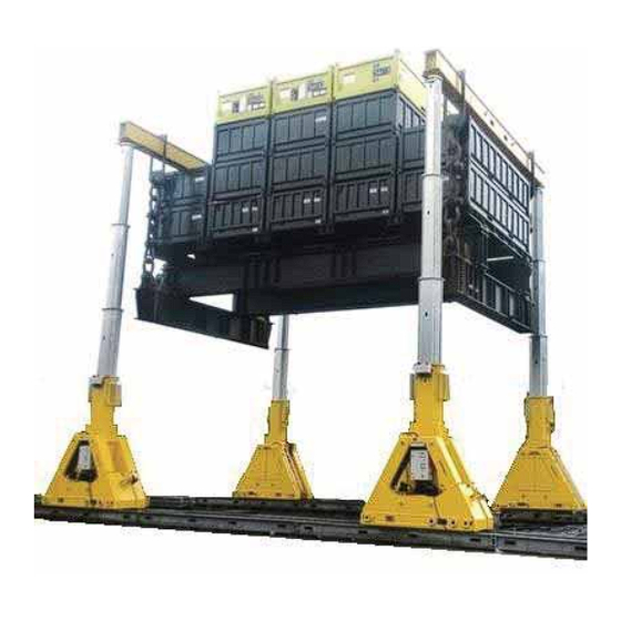
3. System Overview This chapter describes the main functions and components of the System. 3.1. General Side Shift unit Lifting lug Header beam Boom Unit Skid track Remote control console (RCC) Page 24 of 151 Document number: ED. 03622.00.001.R04.ENG Page 24 ED.02518.00.001.R08.ENG... - Page 25 The System is a four point lifting system which can move a heavy load in three directions: Upwards by extending the booms In longitudinal direction by moving the units along the skid tracks In transversal direction by moving the side shift units (if applied) along the header beams Some more properties: The System can put the boom in upright position hydraulically...
- Page 26 The boom consists of a telescopic cylinder system: o the SBL900 extends in two stages o the SBL1100 extends in three stages The boom is provided with guiding pads at the inner side, which o centralise the stages of the boom o enable smooth moving of the stages into each other The guiding pads are adjustable in order to centralise the stages precisely.
- Page 27 Modular header beams composed out of more sections to construct various lengths. Header beams of foreign make may be applied if they have equal material properties their flange dimensions match with the Enerpac beams Page 27 of 151 Document number: ED. 03622.00.001.R04.ENG Page 27 ED.02518.00.001.R08.ENG...
- Page 28 3.1.4. The side shift units The load can be affixed to the header beams by side shift units. Two types of side shift units can be applied: HBS3000 HBS6000 Side shift units enable moving of the load in transversal direction. Therefore, each side shift unit is provided with an electro motor which propels rollers.
- Page 29 3.1.5. The Lifting lugs The load can be affixed to the header beams by lifting lugs. Unlike side shift units, lugs cannot move the load aside. Depending on the mass of the load to be lifted you can apply lifting lugs in double-plate configuration in single-plate configuration 3.1.6.
-
Page 30: System Specifications
3.2. System specifications 3.2.1. Main specifications The specifications listed below are valid both for the SL900 and the SL1100 system. Specification of the power source Voltage 360 to 480 V AC/ 3-phase The units feature automatic phase selection according to the rotation direction of the electric motors Current 16 A per unit... - Page 31 Unit SBL900 Stage 1 700 kN 5060 mm – 8372 mm Stage 2 500 kN 8372 mm – 11360 mm SBL1100 Stage 1 2621 kN 4409 mm – 7060 mm Stage 2 1689 kN 7060 mm – 9724 mm Stage 3 945 kN 9724 mm –...
- Page 32 3.2.3. Dimensions The following information of the main parts of the system is available in Appendixes: Dimensions Weights Technical drawings Part Appendix Skid tracks Appendix F “Drawings for the skid tracks” Units Appendix G “Drawing of the units” Side shift Appendix H “Drawings of the side shift unit”...
-
Page 33: System Configurations
The use of non-Enerpac header beams is allowed as long as those are used in accordance with their own specifications. - Page 34 If you want to put the load on top of the header beams, contact Enerpac. The system is exclusively suitable for lifting with four booms. Call Enerpac for advice when you want to position the load differently. Page 34 of 151 Document number: ED. 03622.00.001.R04.ENG Page 34...
-
Page 35: Service Conditions
3.4. Service conditions The System is intended for hoisting loads. Do not use the System for any other purpose. No alterations may be made to the System. Only use the System as it was delivered. The System is explicitly not intended for transporting people. Attention: Lifting operations with less than four units is strictly prohibited Hazard: Lifting a load with only two units is a high risk operation, hazardous and therefore prohibited:... -
Page 36: Plan A Lifting Operation
Plan a lifting operation In this chapter, the planning activities for a lifting operation are described. 1. Record your planning activities in the checklist given in Appendix A “Checklist for planning a lifting operation”. 2. Make sure the following information is available: Mass of the load Centre of gravity of the load Dimensions of the load... -
Page 37: Ground Bearing Pressure Calculation
4.1. Ground bearing pressure calculation Skid tracks can be put directly on the ground , if the bearing capacity of the ground is sufficient. on a foundation: o to compensate unevenness in the ground o to reduce the bearing pressure. Use is made of the effect that pressure spreads down in an angle of 45 , as shown below. - Page 38 4.1.1. No foundation applied The dimensions of the bearing surface are as follows: Skid height Skid width To calculate the bearing pressure, you may use the following procedure: Parameter Abbrev Value Unit Length Unit length 2.76 m Own mass Unit mass 12 metric tons Skid track Height...
- Page 39 Example: Load to be lifted 1068 metric tons 1068 Ground pressure = 241 metric tons / m Complete the checklist in appendix A “Checklist for planning a lifting operation” with the calculated bearing pressure. Attention: the exerted ground pressure may never exceed the maximum allowed ground bearing pressure.
- Page 40 4.1.2. Foundation applied Timbers of Azobé hard wood can be used as foundation material. Steel plates have to be mounted between the timbers and the skid tracks. The dimensions of the bearing surface are determined as follows: The width of one footprint: Timber height Skid width Width = Skid width + 2 * Timber height...
- Page 41 To calculate the bearing pressure, you may use the following procedure: Parameter Abbrev Value Unit Length Unit length 2.76 m Own mass Unit mass 12 metric tons Skid track Height Skid height 0.3 m Width Skid width 0.3 m Auxiliary material (beams, shackles etc) Aux mass 20 metric tons Safety factor...
- Page 42 Example: Load to be lifted 1068 metric tons Timbers: Width 0.10 m Height 0.10 m 0.03 m Measure of one footprint: Width: Skid width + 2 * Timber height = 0.3 + 2 * 0.1 = 0.5 Length: Unit length + 2 * (Skid height + Timber height) = 2.76 + 2 * (0.3 + 0.1) = 3.56 m L * W: 0.5 * 3.56 = 1.78 m Two footprints :...
- Page 43 > Timber height Timber gap < Timber width mechanical compressive strength > 25 N/mm² without occurrence Timbers of deflection Enerpac strongly recommends adhering to 30N/mm², preferably Azobé wood Steel length > Smin Steel width Timber width Steel thickness > 15 mm...
-
Page 44: Check The Lifting Capacity Of The System
Caution: though all limits for the capacity, lifting height, skew and environmental influences are either calculated or tested by the Enerpac consciously, during lifting operations these parameters may interfere with each other in a negative way. Test situations differ from real life situations! 4.2.1. - Page 45 The effect of eccentricity of the Centre of Gravity on the capacity of the System When the Centre of Gravity (COG) is not in the centre of the System, the capacity of the System will decrease. The figures below give the principle of it. The numbers are fictitious. Assume: a load of 1000 kN a bearing capacity per unit of 250 kN...
- Page 46 Capacity chart of SBL1100 (metric version) ED.03622.70.001.R00.ENG Page 46 of 151 Document number: ED. 03622.00.001.R04.ENG Page 46 ED.02518.00.001.R08.ENG...
- Page 47 Capacity chart SBL900 (metric version) ED.03454.70.001.R00.ENG Page 47 of 151 Document number: ED. 03622.00.001.R04.ENG Page 47 ED.02518.00.001.R08.ENG...
-
Page 48: Side Shift Units And Lifting Lugs
Enter the load in the checklist given in Appendix A “Checklist for planning a lifting operation”. Always determine the force on the side shift units, even for relatively light loads. In case of any doubt, consult Enerpac. Attention: The force on the side shift units shall never exceed their bearing capacity. -
Page 49: The Bearing Capacity Of The Header Beam
The relation between the positions of the suspensions (anchor points) and the allowable load is given in capacity charts. For the capacity charts of Enerpac header beams reference is made to Ref 5 “Technical handbook”. Example how to determine the allowable load of the header beam for two anchor points. - Page 50 Caution: The force on each anchor point shall not increase the capacity of the header beam. Earlier purchased Enerpac / Hydrospex header beams may be applied if their capacity is sufficient. Header beams of foreign make can be applied if their capacity is sufficient, but Enerpac will not take any responsibility for it.
-
Page 51: Side Load
4.5. Side load Side load may endanger the stability of the System. It can be caused by wind skid tracks not level system not mounted plumb slings or shackles not plumb During activities in the open air, wind exerts may put force on the lifted object. Therefore, for every lifting operation the maximum permissible side load has to be calculated. - Page 52 Example of a completed form: Load Properties Operational parameters Load width Total lifting height Load length Sling length Load height Load weight 1250 Header geometry Cross Beam parameters Header width 0.33 Beam width 0.33 Header length 6.00 Beam length 6.00 Header height 0.40 Beam height...
-
Page 53: Install The System
This chapter describes how to install the System, including the preparation of the working location. For torque settings reference is made to Appendix L. Enerpac only guarantees System integrity when exclusively Enerpac products are applied. 5.1. How to hoist parts of the System 5.1.1. - Page 54 Lifting eyes Fork holes Always keep the unit in vertical position 5.1.2. Hoisting the Skid tracks The skid tracks can be hoisted: by a forklift truck. Use the fork holes by a crane. Use the two lifting eyes. 5.1.3. Hoisting the header beams Header beams are provided with lifting eyes.
- Page 55 5.1.4. Hoisting the side shift unit To hoist the side shift units regard the following. The descriptions are given for the HBS6000 only, but are valid for the HBS3000 as well. The side shift units shall only be hoisted using the lifting eyes. When not in use then put the side shift units down horizontally.
- Page 56 To get the side shift unit out of the transportation frame proceed as follows: 1. Put the transportation frame next to the gantry. Preferable apply a forklift. Eventually you can use a crane and use the lifting eyes. 2. At delivery, the side shift units are strapped to the strap-down eyes.
-
Page 57: Place The Skid Tracks
5.2. Place the Skid Tracks Correct positioning of the skid tracks insures that the System is put level on the ground. When the ground is not flat then grade it in advance, to create a solid foundation on which the system can operate safely. - Page 58 5.2.2. Put the skid tracks in place For putting the skid tracks in place, proceed as follows: Put the skid tracks on the foundation and mount them together. Regard the following aspects: Put steel plates between the timbers and the skid tracks Make sure no slack is left between the foundation and the skid tracks.
- Page 59 5.2.3. Align the skid tracks Align the Skid tracks according to the following requirements: Front view Side view Nr Alignment requirement Tolerance The skid tracks shall be in parallel 13 mm (top view) The skid tracks shall be aligned from the start to the end 12 mm (top view) Page 59 of 151...
- Page 60 The skid tracks shall have now skew 0.25° (front view of one skid track) The skid tracks shall not incline 0.2° (side view of one skid track) The skid tracks shall be flat 8 mm over 3 meter (side view of one skid track) The surfaces of the segments of the skid tracks shall be well aligned.
-
Page 61: Put The Units Upon The Skid Tracks
5.3. Put the units upon the skid tracks To put the units upon the skid tracks proceed as follows: 1. Put the units on the skid tracks Regard the hoisting instructions as given in paragraph 5.1.1 “ Hoisting units”. Put all units with the electro cabinet towards the outside. -
Page 62: Connect The Power Cables
5.4. Connect the power cables Connect the power cables to units. Use the sockets on the electrical cabinet. Don’t bother the phase of the power since the units feature automatic phase detection. This assures the correct rotation direction of the electro motors. There are two options for connecting the units: connect each unit individually to the main power. -
Page 63: Put The Boom In Upright Position
5.5. Put the boom in upright position For putting the boom in upright position the system is operated local control. So, use is made of the buttons on the control panel; see section 6.2.1 “The switches and indicators”. The unit has to be connected to electric power. Attention: Never put the boom in upright position or lower it when something is attached to it. - Page 64 Check: nobody is close to the unit no cables can be pinched nothing is attached to the boom Use the buttons on the control panel to raise the boom; see section 6.2. “The Control Panel of the unit”. The tilting cylinders extend. The boom gets in upright position.
- Page 65 Put the shafts back into position and lock them with the spring clips. Play with the buttons on the control panel for fine-positioning, to enable restoring of the shafts. Hazard: A missing shaft may result in an unstable unit foot and thus also an unstable system.
-
Page 66: Mount The Header Beams
5.7. Mount the header beams 5.7.1. Assemble the modular beam When you apply the modular header beam then construct it as follows: 1. Put two sections male / female together and align the holes 2. Mount the connection bolt 3. Mount the flanges of the connection bolt 4. - Page 67 5.7.2. Mount the header beam on top of the boom To mount the header beams on top of the boom proceed as follows: 1. Remove the six bolts at the top of the swivel plate Locking strips 2. Remove the locking strips. bolts bolt Distance...
-
Page 68: Put The Side Shifts On The Header Beams
5.8. Put the side shifts on the header beams To put the side shifts to the header beams, proceed as follows: Mount the cable-guiding wheel at the header beam. Hoist the side shift unit out of the transportation frame. Both types of side shift units are depicted. Remove the locking pins. - Page 69 Place the anchor block. Lock the bolts with the locking pins When you’re going to apply slings then mount the sling tool. Page 69 of 151 Document number: ED. 03622.00.001.R04.ENG Page 69 ED.02518.00.001.R08.ENG...
- Page 70 Connect the cable on the cable reel with the side shift Ensure that the cable is mounted in such a way that it cannot get pinched. Mount the other side shift similarly. Set the moving direction in such a way that side shift units will move in the same direction.
-
Page 71: Mount The Longitudinal Beams
Enerpac provides a solution for mounting longitudinal beams. Contact Enerpac if you want to apply longitudinal beams 5.10. Check the stroke sensor Though the wire of the stroke sensor is not a removable part, its presence and the correct mounting has to be checked due to its vulnerability. -
Page 72: Install The Remote Control Console (Rcc)
5.11. Install the remote control console (RCC) The RCC can communicate with the units: wireless, using radio wired, using data cables 5.11.1. Wireless communication The RCC enables wireless on a radio frequency of 2.4 GHz. No cables have to be connected. BUT: The wireless communication may be disturbed. - Page 73 Proceed as follows: Make sure the RCC is switched off Make sure the power of all units is switched off Connect the data cable to the RS-485 socket of the RCC. Connect the data cable to one of the units. Each units are provided with two RS485 sockets.
- Page 74 5.11.3. Set up the communication To set up the communication between the RCC and the four Units to work, proceed as follows. Reference is made to the controls on the RCC as “RCC[x]”. The layout of the RCC is given on page 81. the Control Panels of the units as “UNIT[x]”.
- Page 75 Switch the same switches to off again Switch the RCC off and on As soon as the communication is established: the text “Engine still” is displayed an asterisk is displayed If the RCC detected data cables then the wireless means are switched off. Now it is possible to control the units.
- Page 76 Each RCC is provided with a unique code. This code is known by the receivers of the units, so they can recognize their Master’s Voice. Enerpac has set this communication configuration initially. The setting is persistent and remains after switching off the power.
-
Page 77: Perform An All-Over Visual Inspection Of The System
Press “LEARN” for two seconds When the tekst “NO ANSWER” disappears from the display of the RCC, the RCC and the unit are connected. Eventually repeat [2] .. [7] for the other units Verify that the number on the RCC match with the numbers on the units, by travelling with the units individually. -
Page 78: How To Control The System
6. How to control the System 6.1. The Emergency buttons The system is provided with emergency buttons. On the control panels of all four units. When the button is pressed: o the unit is switched off o the blue button “Emergency active” is lit o if the unit is in Remote Control then other units which are in Remote Control too are switched off as well. -
Page 79: The Control Panel Of The Unit
6.2. The Control Panel of the unit 6.2.1. The switches and indicators 7. It lit when the 1. Extend and lower power is connected the boom 8. It lit when failure of the motor 2. Tilt and lower the boom 9. - Page 80 6.2.2. Local control mode The control panel of a unit enables the operator to control only the unit on which it is mounted. Other units cannot be controlled. Let’s call this mode “Local Control”. Local control is meant to be used during the setting-to-work phase of the System: to manoeuvre the units into position to put the booms in upright position to manoeuvre the side shifts into position...
-
Page 81: The Remote Control Console (Rcc)
6.3. The remote control console (RCC) The RCC enables the operator to execute a lifting operation on a safe distance to control all units simultaneously Let’s call this mode “Remote control”. Applying the RCC ensures that the moving speeds of the units is synchronized the heights of the booms during a lift operation are kept equal within a tolerance of 24 The RCC cannot control the tilting cylinders, used for putting the boom in upright position. - Page 82 6.3.1. The controls 1 Display: 3 Emergency stop. 2 Connection for fixed wiring load per lifting foot, (RS845). Also used to charge the When pressed, all Units which are in lifting height per foot, batteries. Remote are switched off. (The Units have error messages to be reactivated using their own Control …...
- Page 83 6.3.2. The display C. Direction of the arrow Direction of arrow within the remote control display: Up: Lifting Down: Lowering Right or Left: Travelling direction B. Total load on A. Absolute height of Diagonal: Side shifting the System the cylinders D.
- Page 84 o When the emergency button on a unit was pressed, but only when that unit was on Remote control. Reference is made to section 6.1. “The Emergency buttons”. Battery level The display shows the power level of the battery. The console can operate approximately 8 hours on a fully charged battery. Switch the console off after use and connect it with the 12V loader.
- Page 85 6.3.3. Calibrate the stroke sensor This paragraph describes how to calibrate the stroke sensor, which measures the height of the boom. Reference is made to the layout of the remote control console on page 82. Calibration has to be performed when stroke sensors were changed, so calibration is not part of the daily routine.
- Page 86 Extend the cylinders to the very maximum position Deselect the unit The stroke sensor has been calibrated. The message “Calibration succeeded” is shown. 10. Switch the RCC off. 11. Switch the RCC on. 12. Verify the displayed position. It should be the maximum position. 13.
-
Page 87: Execute A Lifting Operation
7. Execute a lifting operation This chapter describes how to perform a lifting operation. 7.1. Risks and Warnings Good operation of the System is essential for safety. Therefore, address the following subjects: Attention It is of the utmost importance to read this manual carefully before setting up the machine. -
Page 88: Warning Signs On The System
Follow the instructions on labels applied to the system, without question. Hazard Despite all inherent safe design measures, safeguarding and complementary protective measures, there will always be the residual risk of tumbling of the system. 7.2. Warning signs on the System The following signs are applied to the system: The legend of the symbols is given in section 2.3. -
Page 89: Suspend The Load
7.3. Suspend the load For suspending the load regard the following subjects: 1. The anchors on the header beam have to be in line with the hoisting points of the load. Hazard: if the anchors are not in line with the hoisting points, the load will sway as soon as it gets free (front view) -
Page 90: Lift The Load
7.4. Lift the load This section describes how to lift the load. In the procedure below reference is made to the controls on the RCC: “RCC [number of the control as given on page 81]. E.q. RCC[5] means: press the Speed button on the RCC. the Control Panels of the Units: “UNIT [the number of the control as given on page 79]. - Page 91 Reset the measured heights of all units by pressing “zero lift”. The current heights of the cylinders will be taken as the new reference points. The height counters [D] on the display will start counting from zero. Select the travelling speed. Select “low”...
-
Page 92: Move The Load In Longitudinal Direction
7.5. Move the load in longitudinal direction For travelling all four units simultaneously and synchronised, apply the RCC. See section 6.3.1 “The controls”. To move one single unit individually, you can use local control; see section 6.2.2 “Local control mode” the RCC;see section 6.3.1 “The controls”. - Page 93 7.5.2. Synchronize the positions of the units The system keeps the relative positions of the units lined-up automatically. Use is made of a travelling distance measuring device which runs on the skid track. The measuring starts counting at zero every start. Due to the limited resolution of the measuring device, the positions of the units may get out of rectangular formation when the system has stopped moving several times.
-
Page 94: Move The Load In Transversal Direction
7.7. Move the load in transversal direction For moving the load in transversal direction the moving capability of the side shift is applied. To operate the side shifts simultaneously, proceed as follows: 1. Apply the RCC 2. Verify that all checklists have been completed and signed off: Appendix A “Checklist for planning a lifting operation”... -
Page 95: Tilt The Load
The blue unit is passive and stands still. Hazard: This operation has an increased risk of dangerous lateral forces. If you want to perform a tilting operation, first contact Enerpac. An illustrative video of a tilting operation is available on https://www.youtube.com/watch?v=rC1toW6ECfU. - Page 96 To tilt a load, proceed as follows. In the procedure below, the controls of the RCC are indicated like “[x]”. For the layout of those controls see page 81. Apply the RCC Record all activities during the operation using the form given in Appendix D “Recording a lifting operation”.
-
Page 97: Solve Problems
(motor failure) indicator [9] should be dimmed (side shift overload) Are hydraulic leakages visible? Are there any mechanical obstructions? Solve the problem accordingly. Call Enerpac if you need assistance Page 97 of 151 Document number: ED. 03622.00.001.R04.ENG Page 97 ED.02518.00.001.R08.ENG... -
Page 98: List Of Problems And Solutions
Main problems Load value “–300” displayed Faulty or loose wiring Check the wiring (large negative) Call Enerpac All units selected, but none Cylinder at end position? moves up One of the hydraulic motors stopped Press the START button [10] on... - Page 99 If not successful then Contact Enerpac. The table is meant as a first aid kit. Contact Enerpac if you need assistance. Hazard: Performing repairs on the System may cause dangerous effects when not executed by well-skilled personnel.
-
Page 100: Storage
9. Storage Requirements for storage of the System: During short-term storage, especially in the open air, cover the units with a tarpaulin in order keep electrical and other moisture-sensitive components dry. The tarpaulin is not included in the delivery, but can be added as an option. Long-term storage: For long-term storage a dry and closed space is recommended. -
Page 101: Maintenance
Maintenance which is not described in this section can only be performed by or in consultation with Enerpac. Only apply spare parts provided by Enerpac. If parts of foreign make are applied, all guarantees will be void. Page 101 of 151 Document number: ED. -
Page 102: Mechanical
Perform maintenance on the mechanical part according to the list as shown below. Record all activities in Appendix E “ Recording maintenance”. Person Subject Action O (owner) EE (Enerpac expert) 1. Main construction 1.1. Main construction Visual check of all weldings Visual check painting Visual check on corrosion and damages Check all bolts. - Page 103 2.2. Tension the chain Tension the driving chains the driving chains see section 10.1.2 “Tension ” 2.3. Tension the roller Tension the roller chain chains the roller chains see section 10.1.3 “Tension ” 3. Side shift unit 3.1. Lubricate the Lubricate the chain chain see section10.1.4 “Lubricate the side shift units”...
- Page 104 10.1.1. Lubricate the driving chains Chains connect the gearboxes with the driving shafts. To lubricate the chains proceed as follows: Make sure the power supply has been switched of Unlock the front doors and open them doors Visually inspect the chains and the gears chains Clean the chains Lubricate the chain with Kroon Oil multi-...
- Page 105 10.1.2. Tension the driving chains 1. Perform steps [1] .. [3] from section 10.1.1 “Lubricate the driving chains”. The gearbox is affixed to the frame of the unit with 6 bolts which can move in shaft gearbox slotted holes. The bearings of the intermediate shaft are affixed to the frame of the unit with 6 bolts, which can move in slotted holes 2.
- Page 106 10.1.3. Tension the roller chains To tension the roller chains proceed as follows: Hazard During the adjustment, you are underneath the unit. Use lawful hoisting and lifting equipment. Make sure the power supply has been switched of Lift the unit. Verify the slack between the upside of the middle roller and the frame of the unit.
- Page 107 Tension the chains by turning the bolts. Use hand power. Make sure the shaft is kept parallel. Carry on turning until the top of the roll is flush with the frame Caution Tensioning the chain too tight might harm the driving mechanism Tighten the bolts.
- Page 108 10.1.5. Replace the oil of the gearbox 1. Perform a purity test on the oil of the gearboxes Gear boxes 2. Change the oil of the gearbox If the yearly purity test points out, at least every 10 years Use 2.6 litres of oil type “ISO VG 320 Mineral oil”.
- Page 109 10.1.7. Adjust the guiding pads The guiding pads of the booms have to be adjusted periodically, due to wear after replacement The guiding pads are located in the booms on each stage Æ, so for the SBL100 on three spots, for the SBL900 on two spots. At each stage, the inner side of the boom is provided with four sets of steel plates on which guiding pads are mounted: sets of plates...
- Page 110 Adjusting the guiding pads is done stage by stage, by tensioning the adjusting bolts. The procedure has to be executed preferably by two persons. This accurate job should preferably be executed by Enerpac people. To adjust the guiding pads proceed as follows: 1.
- Page 111 10.1.8. Booms / Guiding pads Procedure: Saturate a rag and lubricate the booms on their running surfaces (mating surface of the guide pads) with synthetic motor oil for instance 10W40. Remarks: In case of vibration of the booms during operation, execute this procedure also. In case of contamination of the running surface(s) by for instance sand, clean the running surfaces and lubricate the booms again.
-
Page 112: Hydraulic
10.2. Hydraulic All inspections up to yearly have to be performed if the system has been idle for at least 12 months. For repairs reference is made to section 2.6. “Working on the hydraulic system”. The system shall only be returned to service when approved by a qualified person as described that section. - Page 113 Enerpac strongly advises to apply parts as bought from Enerpac. Hazard Applying parts which to not apply to the specifications may cause hazards to personnel and the system Perform maintenance on the mechanical part according to the list as shown below.
- Page 114 1.5. Oil Change oil if Take an oil sample to analyze necessary Replace the hydraulic oil. Or after 2000 See section 10.2.1 “Drain the oil” and running hours Section 10.2.2 “Filling the tank” Check the oil level 1.6. Hydraulic filter And if Check and replace the filter element.
- Page 115 3. Housing 3.1. Common Check on damages and paint Check if the bolts are still tightened Replace all seals, door seals and inspection hatches Grease the hinges and locks Replace engine feet 4. Cylinders 4.1. Common Check on leakages Check if the bolts are still tightened Replace all seals Grease the bearings Page 115 of 151...
- Page 116 10.2.1. Drain the oil The oil in the sump has either to be refreshed or a purity test has to be performed. The minimum requirement is that the purity of the medium is in accordance with class 7 of NAS 1638. Proceed as follows: 1.
- Page 117 10.2.2. Filling the tank To fill the tank, proceed as follows: 1. Make sure the cylinder of the unit is fully pulled in 2. Use the fill/bleed opening to fill the tank with oil. Use oil type “Shell Tellus T32 or Shell Tellus Artic”. Filler cap Caution Do not fill the tank over the maximum.
- Page 118 To replace the filter element, proceed as follows: Unscrew the return filter cap Remove the internal filter element Put a new filter element. To ensure correct operation, only replace with an element with equal brand and type. Use Hydac return filters. The exact type is listed on the parts list of the machine. Page 118 of 151 Document number: ED.
-
Page 119: Electrical
Perform maintenance on the electrics of the system according to the list below. Record all activities in Appendix E “ Recording maintenance”. Person Subject Action O (owner) EE (Enerpac expert) 1. Electro motor 1.1. General Check on damages Wipe it clean and free from dust 2. Cables and connectors 2.1. -
Page 120: Quality
11. Quality Not applicable 12. Recycling the machine To recycle the machine at the end of its lifetime, proceed as follows: Drain and collect the hydraulic oil and other fluids separately, if applicable. Remove the batteries. Remove the electric components and electric wiring. Remove the metal components. -
Page 121: Index
13. Index calibrate, 85 device, 19, 25, 26, 93, gravity, 35, 36, 63 calibration, 85 98, 100, 104 grease, 104, 107, 149 dimensions, 27, 38, capability, 94 grinding, 19 40, 44, 52 accident, 16, 20, 35 capacities, 31, 44 grooves, 61 direction, 8, 25, 28, accretion, 30 capacity, 23, 30, 36,... - Page 122 lift, 34, 45, 81, 83, protection, 21, 22, tensioning, 105, 85, 90, 91, 99, 125 NEN-EN, 7 lifting, 3, 16, 23, 25, protective, 15, 22 theodolite, 96 NEN-EN-ISO, 7 26, 29, 31, 32, 34, 36, timbers, 23, 40, 41, 39, 42, 44, 48, 50, 51, 43, 55, 57, 58 52, 53, 54, 55, 56, 63, torque, 53, 123, 149...
-
Page 123: Appendices
Appendices A. Checklist for planning a lifting operation Project Project Customer Location Date 2. Operation type † Lift / lower † Move in longitudinal direction † Move in transversal direction 3. Ground bearing pressure † m² σ ….. Tonne/ Allowable ground bearing pressure ( toe) 4. -
Page 124: Checklist For Installing The System
B. Checklist for installing the System 1. Project Project Customer Location Date 2. Planning † Checklist A “Checklist for planning a lifting operation” was completed and signed off 3. Foundation Foundation underneath skid tracks has been put in accordance with the instructions in this †... - Page 125 page 2/2 8. Visual inspection † Visual inspection: no excessive rust. † Visual inspection: no parts of the system are damaged † Visual inspection of the hydraulic components: no oil leakages Running surfaces of the skid tracks are clean. † (Dirt may cause the units slip) †...
-
Page 126: Final Checks
C. Final checks 1. Project Project Customer Location Date 2. Installation † Checklist B “Checklist for installing the System” was completed and signed off 3. Inspect the System † No parts of the portal lift are damaged † No leakages of the hydraulic components Drop-zone is cordoned off. - Page 127 Part 2/2 4. Check the suspension of the load The anchors on the header beam are in line with the hoisting points of the load. † (front view) The lifting straps are short. † (front view) The header beam are level †...
-
Page 128: Recording A Lifting Operation
D. Recording a lifting operation 1. Project Project Customer Location Date 2. Recording of activities Activity Time The checklists have been completed and are signed off: † Appendix C “Final checks” has been completed and signed off Page 128 of 151 Document number: ED. - Page 129 Part 2/3 Activity Time 3. Commitment Date: Executed by Signature Date: Approved by Signature Page 129 of 151 Document number: ED. 03622.00.001.R04.ENG Page 129 ED.02518.00.001.R08.ENG...
-
Page 130: Recording Maintenance
Recording maintenance Use the table below for recording all maintenance activities, accordance with section 10. “Maintenance”. a. Mechanical: Person Date Subject Action 1. Main construction 1.1. Main construction Visual check of all weldings Visual check painting Visual check on corrosion and damages Check all bolts. - Page 131 b. Hydraulical: Subject Action Person Date 1. Electro motor, tank and cooler 1.1. Motor Check on oil leakage, damages and paint work Check if the bolts are still tightened Check on damages Wipe it clean and free from dust 1.2. Hydraulic tank Check on oil leakage, damages and paint work Check if the bolts are still tightened Replace all seals...
- Page 132 3. Housing 3.1. Common Check on damages and paint Check if the bolts are still tightened Replace all seals, door seals and inspection hatches Grease the hinges and locks Replace engine feet 4. Cylinders 4.1. Common Check on leakages Check if the bolts are still tightened Replace all seals Grease the bearings c.
-
Page 133: Drawings For The Skid Tracks
F. Drawings for the skid tracks Page 133 of 151 Document number: ED. 03622.00.001.R04.ENG Page 133 ED.02518.00.001.R08.ENG... - Page 134 Page 134 of 151 Document number: ED. 03622.00.001.R04.ENG Page 134 ED.02518.00.001.R08.ENG...
-
Page 135: Drawing Of The Units
G. Drawing of the units Page 135 of 151 Document number: ED. 03622.00.001.R04.ENG Page 135 ED.02518.00.001.R08.ENG... - Page 136 Page 136 of 151 Document number: ED. 03622.00.001.R04.ENG Page 136 ED.02518.00.001.R08.ENG...
-
Page 137: Drawings Of The Side Shift Units
H. Drawings of the side shift units Page 137 of 151 Document number: ED. 03622.00.001.R04.ENG Page 137 ED.02518.00.001.R08.ENG... - Page 138 Page 138 of 151 Document number: ED. 03622.00.001.R04.ENG Page 138 ED.02518.00.001.R08.ENG...
-
Page 139: Drawings Of The Lifting Lug
Drawings of the lifting lug Page 139 of 151 Document number: ED. 03622.00.001.R04.ENG Page 139 ED.02518.00.001.R08.ENG... -
Page 140: Hydraulic Fluid Safety Information
J. Hydraulic fluid safety information Page 140 of 151 Document number: ED. 03622.00.001.R04.ENG Page 140 ED.02518.00.001.R08.ENG... - Page 141 Page 141 of 151 Document number: ED. 03622.00.001.R04.ENG Page 141 ED.02518.00.001.R08.ENG...
- Page 142 Page 142 of 151 Document number: ED. 03622.00.001.R04.ENG Page 142 ED.02518.00.001.R08.ENG...
- Page 143 Page 143 of 151 Document number: ED. 03622.00.001.R04.ENG Page 143 ED.02518.00.001.R08.ENG...
-
Page 144: Kroon Oil Multi Purpose Grease 3
K. Kroon Oil Multi purpose grease 3 Page 144 of 151 Document number: ED. 03622.00.001.R04.ENG Page 144 ED.02518.00.001.R08.ENG... - Page 145 Page 145 of 151 Document number: ED. 03622.00.001.R04.ENG Page 145 ED.02518.00.001.R08.ENG...
- Page 146 Page 146 of 151 Document number: ED. 03622.00.001.R04.ENG Page 146 ED.02518.00.001.R08.ENG...
- Page 147 Page 147 of 151 Document number: ED. 03622.00.001.R04.ENG Page 147 ED.02518.00.001.R08.ENG...
- Page 148 Page 148 of 151 Document number: ED. 03622.00.001.R04.ENG Page 148 ED.02518.00.001.R08.ENG...
- Page 149 Page 149 of 151 Document number: ED. 03622.00.001.R04.ENG Page 149 ED.02518.00.001.R08.ENG...
-
Page 150: Torque Settings
L. Torque settings Inspect all bolt joints which may pose a hazard to people and machines at fixed intervals and check their torque. Apply the torque values unless indicated otherwise on the drawing. Course pitch Fine pitch [Nm] [Nm] (Copper- (Copper- Nominal Strength... - Page 151 Course pitch Fine pitch [Nm] [Nm] (Copper- (Copper- Nominal Strength grease) grease) size class 0.08 0.08 10.9 12.9 10.9 12.9 1060 10.9 1070 1310 12.9 1250 1530 1000 1280 10.9 1450 1820 12.9 1700 2130 1400 1700 10.9 1950 2430 12.9 2300 2840...
Need help?
Do you have a question about the SBL1100 and is the answer not in the manual?
Questions and answers
need parts list for the cylinder