Table of Contents
Advertisement
Quick Links
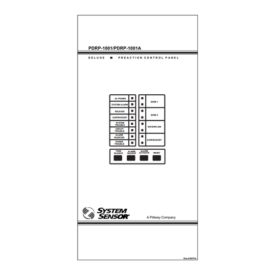
PDRP-1001/PDRP-1001A
D E L U G E
P R E A C T I O N C O N T R O L P A N E L
AC POWER
SYSTEM ALARM
RELEASE
SUPERVISORY
SYSTEM
TROUBLE
CIRCUIT
TROUBLE
ALARM
SILENCED
POWER
TROUBLE
TONE
SILENCE
SILENCE
ZONE 1
ZONE 2
WATERFLOW
SUPERVISORY
ALARM
ALARM
ACTIVATE
RESET
A Pittway Company
Doc.# 50734
ECN 97-514
Advertisement
Table of Contents

Subscribe to Our Youtube Channel
Related Manuals for Pittway System Sensor PDRP-1001


Summary of Contents for Pittway System Sensor PDRP-1001
- Page 1 P R E A C T I O N C O N T R O L P A N E L AC POWER ZONE 1 SYSTEM ALARM RELEASE ZONE 2 SUPERVISORY SYSTEM TROUBLE WATERFLOW CIRCUIT TROUBLE ALARM SILENCED SUPERVISORY POWER TROUBLE TONE ALARM ALARM SILENCE ACTIVATE RESET SILENCE A Pittway Company Doc.# 50734 ECN 97-514...
- Page 2 PDRP-1001/PDRP-1001A Document 50734 Rev B 12/21/97...
-
Page 3: Table Of Contents
Table of Contents I NFPA Standards ..............4 II Additional Information ...........4 1.0 The PDRP-1001/PDRP-1001A ............5 1.1 Features ......................5 1.2 Circuits ......................5 1.3 Optional Boards .................... 7 1.4 Remote Annunciator ..................8 1.5 Optional Meters ..................... 8 1.6 Specifications....................9 2.0 System Operation ................. -
Page 4: I Nfpa Standards
NFPA Standards This control panel complies with the following NFPA standards: NFPA 13 Sprinkler Systems NFPA 15 Water Spray Systems NFPA 16 Foam-Water Deluge and Foam-Water Spray Systems NFPA 72 Central Station Signaling Systems (Automatic, Manual, and Waterflow). Protected Premises Unit (Requires NOTI-FIRE 911AC DACT or MS5012 Slave Communicator).* NFPA 72 Local (Automatic, Manual, Waterflow and Sprinkler Supervisory) Fire Alarm Systems. -
Page 5: The Pdrp-1001/Pdrp-1001A
1.0 The PDRP-1001/PDRP-1001A Features • Microprocessor-controlled • RMS regulated output power, 2.25 amps • Alarm and trouble resound • 7 amp/hour to 15 amp/hour battery options, • Four Style B/D Initiating Device Circuits up to 90 hours standby • Two Style Y/Z Notification Appliance Circuits •... - Page 6 Figure 1.0-1: PDRP-1001/PDRP-1001A Installation Diagram PDRP-1001/PDRP-1001A Document 50734 Rev B 12/21/97...
-
Page 7: Optional Boards
Optional Boards The PDRP-1001/PDRP-1001A has mounting slots for two option boards. Any two of the three option modules may be installed. Transmitter Module (4XTM NOTIFIER) The Transmitter Module provides a supervised output for local energy municipal box transmitter (for NFPA 72-1993 Auxiliary Fire Alarm System) and alarm and trouble reverse polarity circuits (for NFPA 72-1993 Remote Station Fire Alarm System). -
Page 8: Remote Annunciator
Transmitter Module (4XTM NOTIFIER) For Local Energy Municipal Box service (NFPA 72 Auxiliary Fire Alarm System) Supervisory current: 5.0 mA. Trip current: 0.35 amps (subtracted from Notification Appliance power). Coil Voltage: 3.65 VDC. Coil resistance: 14.6 ohms. Maximum allowable wire resistance between panel and trip coil: 3 ohms. Municipal Box wiring can leave the building. -
Page 9: Specifications
Specifications AC Circuit AC Power For PDRP-1001/PDRP-1001A: 120 VAC, 50/60 Hz, 1.2 amps Breaker Wire size: minimum #14 AWG with 600V insulation Battery (lead acid only) Maximum Charging Circuit: 27.6V, 1.5 amps Maximum Battery Capacity: 15 AH. (Batteries larger than 12 AH require Notifier #BB-17 or other UL listed battery cabinet.) Initiating Device Circuits Power-limited circuitry... - Page 10 Cabinet = 5.375" Backbox = 4.750" Door = 14.625" Backbox = 14.5" Door = 16.125" Backbox = 16" Optional Trim Ring TR-4XR Figure 1.6-1: Cabinet Dimensions PDRP-1001/PDRP-1001A Document 50734 Rev B 12/21/97...
-
Page 11: System Operation
2.0 System Operation System Status LEDs Alarm, Trouble and Supervisory LEDs will flash on and off until the event(s) has been acknowledged (TONE or ALARM SILENCE), at which point the LED will illuminate steadily. AC POWER Green LED that illuminates steadily to indicate presence of AC power. -
Page 12: Control Switches
Control Switches Tone Silence Acknowledge alarms, troubles and supervisories. The panel has alarm and trouble resound with LED flash of new conditions. The flashing trouble LED(s) illuminate steadily on TONE SILENCE and the piezo sounder silences. A second trouble will resound the piezo. The piezo has three distinct sounds for alarm, trouble, and supervisory. -
Page 13: Supervisory
Supervisory Zone 4 is always used for monitoring supervisory devices (such as valve tamper switches). A short circuit on this zone (activation of a N.O. contact) will cause the supervisory LED and the zone 4 yellow LED to flash. The piezo sounder will generate a unique Pressing TONE SILENCE will silence the piezo and cause the supervisory LED to illuminate steadily, but the Zone 4 Trouble LED will continue to flash . -
Page 14: Installation Procedure
3.0 Installation Procedure General Carefully unpack the system and check for shipping damage. Mount the cabinet in a clean, dry, vibration- free area in which extreme temperatures are not encountered. The location should be readily accessible with sufficient room for easy installation and maintenance. Locate the top of the cabinet approximately five feet above the floor with the hinge mounting on the left. -
Page 15: Initiating Device Circuits
Initiating Device Circuits Zones Wire all alarm initiating devices sequentially for proper supervision. Initiating devices include: heat, photoelectric, and ionization type detectors; and waterflow alarm devices. Refer to the Device Compatibility Chart, Appendix B. Notes: Observe polarity when connecting polarized devices. All circuits are supervised and power limited. -
Page 16: 4-Wire Smoke Detector Connections
4-Wire Smoke Detector Connections Refer to the Device Compatibility Chart (Appendix B), for suitable 4-wire smoke detectors. 24 VDC (+) 24 VDC (+) Common (-) Common (-) Black IDC(+) IDC(+) IDC(-) IDC(-) UL Listed Listed 4.7K, 1/2-Watt UL-listed 24 VDC Power Four-Wire Smoke Detectors Supervision... -
Page 17: Output Circuits
Output Circuits Notification Appliance Circuits This control panel can provide two Style Y/Z Notification Appliance Circuits and two Style Y Releasing Circuits (see Section "Dip Switch Location and Descriptions" for DIP switch configuration). Each circuit is capable of 1.5 amps of current. Total current drawn from all four circuits cannot exceed 2.25 amps. Refer to the Device Compatibility Chart, Appendix B. -
Page 18: Power
Alarm Relay One Form-C dry alarm contact is provided in the basic panel for controlling supplementary devices. It is rated 2 amps at 30 VDC and 0.5 amps at 30 VAC (resistive) and is non-silenceable when an alarm occurs. See below for terminal location. Trouble Relay One Form-C dry trouble contact is provided in the basic panel for controlling supplementary devices. - Page 19 AC Power Primary power required for the PDRP-1001/PDRP-1001A panel is 120 VAC, 50/60 Hz, 1.2 amps. Overcurrent protection for this circuit must comply with Article 760 of the National Electrical Code (NEC) and/or local codes. Use #14 AWG or larger wire with 600 volt rating. Battery Power Observe polarity when connecting battery.
-
Page 20: Optional Modules
Optional Modules The fire control panel has two module connectors - J5 and J8. Three modules are available for the panel and they can be used in any combination, including duplicate modules. The corresponding option jumper must be cut before installation of an optional module, to enable module supervision. OPT1 Jumper Cut to install module on J5. - Page 21 Installing Option Modules Insert the two stand-offs (provided) into the holes located on the right-side edge of the main board. Carefully align the pins on the main board with J1 and/or J2 on the option board. Insert screw through the option board until it is secured on the stand-offs.
- Page 22 Transmitter Module -- 4XTM (NOTIFIER) Polarities shown in activated positions. The wiring of this module must follow the requirements as specified in the "General" Section , "UL Power Limited Wiring Requirements." Remote Alarm Power Limited Circuit Remote Trouble No Connection Municipal Box * Non-Power Limited Circuit TBL Jumper...
- Page 23 Zone Relay Module -- 4XZM (NOTIFIER) Non-power limited and power limited wiring must have a minimum distance of 0.25" wire to wire. If this module is used to drive non-power limited and power limited circuits, please follow the instructions below: Relay #1 through #4 will activate with Out- put #1 through #4 and remain latched unless jumper "LATCH"...
- Page 24 LED Interface Module -- 4XLM (NOTIFIER) The wiring of this module must follow the requirements as specified in the Section "UL Power Limited Wiring Requirements." +24V Out #1 Out #2 Out #3 Out #4 System Trouble Sound Resound Connect to corresponding terminals of RZA-4X Remote Annunciator.
-
Page 25: Dip Switch Location And Descriptions
Dip Switch Location and Descriptions For DIP switch settings, refer to the Section "Setting Mode of Operation." Battery Fail Micro Fail LED Ground Fault LED Slide Switch to "ON" position to select the desired options (refer to the Section "Setting Mode of Operation" .) DIP Switches Switch 3: Discharge timer... -
Page 26: Setting Mode Of Operation
Setting Mode of Operation Basic Program Select the desired mode of operation and set SW1 DIP switches 1 and 2 per the appropriate column. Mode #4 Mode #1 Mode #2 Mode #3 Single Hazard Dual Hazard Dual Hazard Single Hazard Two Zone Cross Zone Combined Release... -
Page 27: Appendix A: Power Calculations
Appendix A: Power Calculations Table A-1: Standby Battery Requirements The Standby Battery Current figure obtained in Table A - 1 represents the amount of current that must be supplied by the secondary power source (batteries) to sustain control panel operation for one hour. Basic Control Panel 88 mA Control panel with AC power off, System Trouble LED and audible trouble sounder on. - Page 28 Table A-2: Ampere-Hour Calculations Standby Battery Current Standby Time Convert the total from Table 1 24, 60, or 90 hours to amps and enter here Standby amps hours amp/hours Alarm Enter 0.25 for 5 minutes in alarm or amp/hours 0.5 for 10 minutes in alarm Total amp/hours Add Standby and Alarm amp/hours needed...
-
Page 29: Appendix B: Device Compatibility Chart
Appendix B: Device Compatibility UL Listed Four-Wire Smoke Detectors FM-Approved Releasing Devices (Notifier's RP-1001) 24 VDC Door Holders Solenoid Group [A] Skinner solenoid valve Model LV2LBX25, 24 VDC, 11 WATTS, 458 mA, 1/2 in. NPS, 5/8 in. orifice. Solenoid Group [B] These valves are interchangeable. ASCO solenoid valve Model T8210A107, 24 VDC, 16.8 Watts, 700 mA, 1/2 in. - Page 30 UL Listed Notification Appliances Control panels supplying Special Application (FWR, Filtered) power must use the notification appliances, relays or door holders listed in the corresponding tables. Notes: 1) All currents are in Milliamperes and worst case average. 2) Nominal Operating voltage. 3) Refer to installation instructions for more information.
- Page 31 UL Listed Notification Appliances Control panels supplying Special Application (FWR, Filtered) power must use the notification appliances, relays or door holders listed in the corresponding tables. Notes: 1) All currents are in Milliamperes and worst case average. 2) Nominal Operating voltage. 3) Refer to installation instructions for more information.
- Page 32 UL Listed, Compatible Two-Wire Smoke Detectors for Notifier Control Panels PDRP-1001/PDRP-1001A Document 50734 Rev B 12/21/97...
-
Page 33: Appendix C: Nfpa Standard Specific Requirements
Appendix C: NFPA Standard-Specific Requirements The fire control panel has been designed for use in commercial, industrial, and institutional applications and meets the requirements for service under the National Fire Protection Association (NFPA) Standards outlined in this appendix. The minimum system components required for compliance with the appropriate NFPA standard are listed below. - Page 34 Figure C-1A: NFPA 72 Signaling Systems for Central Station Service (ProtectedPremises Unit) and Remote Station Protective Service NOTI-FIRE 911AC DACT* - for connection to a Central Station Receiver or Protected Premises Receiving Unit. This unit must be installed as illustrated below. For additional information on the 911AC, refer to document 74-06200-005.
- Page 35 Figure C-1B: NFPA 72 Signaling Systems for Central Station Service Program the Fire•Lite MS-5012 for slave application. Reference the Installation Manual for additional information. AC Wiring for DACT/FACP must be connected to the same circuit. PDRP-1001/PDRP-1001A Document 50734 Rev B 12/21/97...
- Page 36 Figure C-2: NFPA 72 Auxiliary Fire Alarm System All connections are power limited and supervised. This application is not suitable for separate transmission of sprinkler supervisory or trouble conditions. Note: Maximum loop resistance allowed for wiring from control panel to Municipal Box is 3 ohms. Municipal Box Circuit Gamewell Model M34-56...
- Page 37 Figure C-3: NFPA 72 Remote Station Fire Alarm System Intended for connection to a polarity reversal circuit of a remote station receiving unit having compatible ratings. All connections are power limited and supervised with the exception of the reverse polarity loop. Supervision of the loop is the responsibility of the receiver.
-
Page 38: Troubleshooting Table
Troubleshooting Table i t c ) s l l l a e i f i r i l l a r i c . t i a t l , t i c r i i t o c i f i t a i l p c r i... - Page 39 NOTES PDRP-1001/PDRP-1001A Document 50734 Rev B 12/21/97...
-
Page 40: Limited Warranty
This warranty replaces all previous warranties and is the only warranty made by S YSTEM ® . No increase or alteration, written or verbal, of the obligation of this warranty ENSOR is authorized. A Division of Pittway 3825 Ohio Avenue, St. Charles, Illinois 60174 1-800-SENSOR2, FAX: 630-377-6495 PDRP-1001/PDRP-1001A Document 50734 Rev B...
Need help?
Do you have a question about the System Sensor PDRP-1001 and is the answer not in the manual?
Questions and answers