
Summary of Contents for Stulz Air Booster 2
- Page 1 Air Booster 2 Operating instructions Index IT30I Issue 10.2018 Fan assisted floor tiles for data centers 230/1/50-60...
-
Page 2: Air Booster
A I R B O O ST E R 2 A B O U T S T U L Z G M B H Since it was founded in 1947, the STULZ company has evolved into one of the world’s leading system suppliers of air-conditioning technology. - Page 3 It's the result of decades of research and design studies, with a fine search of materials and technologies to obtain an high quality unit. The CE mark guarantees that the STULZ products satisfy the requirements of the European Machinery Directive for safety.
- Page 4 A I R B O O ST E R 2 STULZ reserves the right to update the product and the relevant manual without having to update products and manuals sold previously except under exceptional circumstances. Contact your local STULZ partner when requesting or receiving any updates of instruction manuals or cor- rections when which are considered to be integral parts of the manual.
-
Page 5: Table Of Contents
11. Uninstalling and disposal of the unit ..............34 12. Accessories .......................35 12.1. Light duty grille - ACTBALDG ......................36 12.2. Heavy duty grille - ACTBAHDG ......................36 12.3. Installation of the grille ..........................37 © STULZ SpA . – all rights reserved EN/10.2018/IT30I... -
Page 6: Introduction
Air Booster 2 units are meant to supply a suitable flow of cold air to all servers to ensure their reliability and optimum working conditions. -
Page 7: Safety Directions
2.1. Introduction This Air Booster 2 unit has been designed and built for a professional use according to applicable regulations. Please check the complete list of applicable regulations in the attached CE and UL conformity declaration. -
Page 8: Residual Hazard
OFF. Be sure that the main switch will not re-activated during maintenance 2.4. Labels DANGER: MOVING DANGER: HIGH VOLTAGE COMPONENTS LIFT THE UNIT USING DANGER: HOT COMPONENTS THESE HANDLES EN/10.2018/IT30I © STULZ SpA – all rights reserved... - Page 9 Labels on the packaging of the unit, on both sides Maximum 5 CE marked UL marked units one above the other Keep dry Position Fragile Do not step Lift cart here © STULZ SpA . – all rights reserved EN/10.2018/IT30I...
-
Page 10: Intended And Non-Intended Use
The Air-Booster2 is used to control airflow and is designed for indoor installation. Any use beyond this is not deemed to be use as intended. STULZ is not liable for any damage resulting from such misuse. The operator alone bears the risk. -
Page 11: Precautions When Handling The Unit
With ex-works delivery conditions, carrier is the sole responsible for any damage caused during transport. STULZ is not responsible for damages to the goods caused by the carrier, but will do everything in its power to assist clients on those situations. -
Page 12: Storage
• Keep original packing (pallet and protections) for future shipments. ATTENTION Use original packing to ship the unit to any other destination If packing disposal is necessary, we remind to dispose different materials suitably EN/10.2018/IT30I © STULZ SpA – all rights reserved... -
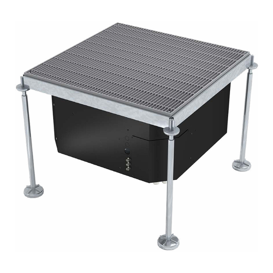
Page 13: Description
If this system can not deliver the airflow required by the servers to where it is needed, the floor tile can be replaced by an Air Booster 2. The reasons for an adjustment of the air supply can be caused for example by changes in the configuration of the rack (conversion to high density racks) or by changes in the raised floor which lead to pressure drops which were originally not calculated. - Page 14 Three temperature sensors have to be installed in the high part, the middle and in the lower part of the rack. The fan speed of the Air Booster 2 is proportional to the average temperature of the three temperature sensors of the rack, or is proportional to the maximum temperature detected from the sensors, according to the controller settings.
-
Page 15: Components
Temperature probe 1 Temperature probe 2 Temperature probe 3 © STULZ SpA . – all rights reserved EN/10.2018/IT30I... -
Page 16: I/O Controller
Air Booster 2 of type BAF60FD220 are equipped with the controller described in the following. In the factory setting, Air Booster 2 operates on temperature control. Once the system is in "System ON" mode, the unit controls fan speed automatically, in dependence of the measured temperature values. -
Page 17: Quick Display Menu (Actual Value Display)
3. Press SET to go back to the list. 4. Press SET + UP to go back to the main screen. © STULZ SpA . – all rights reserved EN/10.2018/IT30I... -
Page 18: Basic Display And Setpoint
2. The temperature (SPt) or pressure (SPb) setpoint is displayed and °C/°F led starts to flash; 3. To change the value, press UP and DOWN keys; 4. To save new setpoint and return to the standard display, press SET or wait 30 seconds to exit the programming. EN/10.2018/IT30I © STULZ SpA – all rights reserved... -
Page 19: Selection Menu
With the key SET you can switch between the display of the actual value and the setpoint even in the locked mode. 3. If a key (not up arrow) is pressed for more than 3 seconds, “POF” appears. © STULZ SpA . – all rights reserved EN/10.2018/IT30I... -
Page 20: Parameters
(differential for high temp alarm to be restored) Temperature alarm delay (in normal mode) 0 to 255 seconds 20 sec Temperature alarm exclusion at power on 0 to 255 seconds 60 sec EN/10.2018/IT30I © STULZ SpA – all rights reserved... -
Page 21: Setting The Operating Mode
The probe value is displayed only if the probe is connected. If the probe is not used and not connected, “nu” (not used) label appears on the display. © STULZ SpA . – all rights reserved EN/10.2018/IT30I... -
Page 22: Temperature Control
Upon switch-on, in “System ON” state, the controller will wait for the delay upon start-up time (ton) before starting to regulate. This not only applies to the switch-on, but also when switching from “System OFF” to “System Stand By” or to “System ON”. EN/10.2018/IT30I © STULZ SpA – all rights reserved... -
Page 23: Alarms
The alarm is also disabled by: K1 relay and bring An-out a. Instrument restart shutdown AO1 and AO2 to 0 V. b. Cycle of Stand-by/Off followed by restart. © STULZ SpA . – all rights reserved EN/10.2018/IT30I... - Page 24 • The display of the relative notification alarm (in flashing mode), on a rotating basis together with existing alarms alternated with displayed probe by default (Lod). If the display also shows faulty probe alarm, the display will show the alarms on a rotating basis. EN/10.2018/IT30I © STULZ SpA – all rights reserved...
-
Page 25: Modbus Rtu Datapoint
05: Write Single Coil 06: Write Single Holding Register The following parameters may have to be adjusted on the controller of the unit: • Modbus-Address: Adr • Baud Rate selection: br © STULZ SpA . – all rights reserved EN/10.2018/IT30I... -
Page 26: Technical Data
Maximum Airflow 5200 Power consumption* 0,075 Operating current (OA)* Maximum operating current (FLA) Raised floor overpressure* External sound pressure level** dB(A) Weight Height x Width x Depth 598 x 598 x 260 EN/10.2018/IT30I © STULZ SpA – all rights reserved... -
Page 27: Drawings
Only skilled personnel may repair, inspect or maintain the units. The installation of an Air Booster 2 is similar as fixing an air diffusion grill on the false floor. It's necessary a minimum space of 150 mm under the unit to guarantee the correct operation of the fan. Please follow the indications below. - Page 28 (heavy duty grille) or ACTBALDG (light duty grille)). The grille has to be place above the unit using 4 grains that can be regulated in order to correspond with the height of the floor. For more information please refer to chapter "Accessories". 4 x adhesive protection EN/10.2018/IT30I © STULZ SpA – all rights reserved...
-
Page 29: Adjusting The Airflow Direction
7. A power supply should be provided near the Air Booster 2 which will help to easily rig up the system connections. Connect the power supply, as shown in paragraph "Electrical Connections"... -
Page 30: Electrical Connections
2 manual. Size of main switch must be determined according to the maximum current consumption of the components. • To make electrical connection of power supply, use cables with section suitable to the power EN/10.2018/IT30I © STULZ SpA – all rights reserved... -
Page 31: Start-Up
Checks after commissioning • Check the current absorption of the fan and compare it with the values indicated in the technical data. • Check the electrical absorption of all the components. © STULZ SpA . – all rights reserved EN/10.2018/IT30I... -
Page 32: Switching Off
The unit must be switched off immediately after the measuring procedure. The electric box might be hot. Maintenance operations may only be performed by authorised and qualified technicians. EN/10.2018/IT30I © STULZ SpA – all rights reserved... -
Page 33: Preventive Maintenance Schedule
Remove dust with a vacuum cleaner. Clean the internal parts with a liquid detergent and compressed air not greater than 4 bar, with the unit suitably earthed. © STULZ SpA . – all rights reserved EN/10.2018/IT30I... -
Page 34: Troubleshooting
The following are the instructions for proper disposal of the unit during the various phases of its life. For further clarification or additional information, please contact info@stulz.it. EN/10.2018/IT30I © STULZ SpA – all rights reserved... -
Page 35: Accessories
Heavy Duty version is designed for a higher point load, and is preferable when the area in front of the racks is for instance loaded by the wheels of transport trolleys. © STULZ SpA . – all rights reserved EN/10.2018/IT30I... -
Page 36: Light Duty Grille - Actbaldg
33 ÷ 44mm Concentrated load over 25 mm x 25 mm 4,5 kN Width 598 mm Height 598 mm Threaded pins M8x20 Colour RAL 7047 Material Steel Floor grille structural class EN 13264:2001 EN/10.2018/IT30I © STULZ SpA – all rights reserved... -
Page 37: Installation Of The Grille
12.3. Installation of the grille The grille has to be installed above the Air Booster 2 unit, using 4 threaded pins, that can be regulated using an hexagonal 4 mm Allen key in order to correspond with the height of the floor. - Page 38 3. Lift and move the grille (picture number 2). 4. Put the grille on the floor (picture number 3). INFORMATION Inside the packaging of the fan module, one lifting key is present. 1 - ACTBALDG 1 - ACTBAHDG EN/10.2018/IT30I © STULZ SpA – all rights reserved...
- Page 39 FRANCE STULZ GROEP B. V. STULZ Austria GmbH Tel. +34 (91) 517 83 20 STULZ France S. A. R. L. Tel. +31 (20) 54 51 111 Tel. +43 (1) 615 99 81-0 Fax +34 (91) 517 83 21 Tel. +33 (1) 34 80 47 70...
Need help?
Do you have a question about the Air Booster 2 and is the answer not in the manual?
Questions and answers