Advertisement
Quick Links
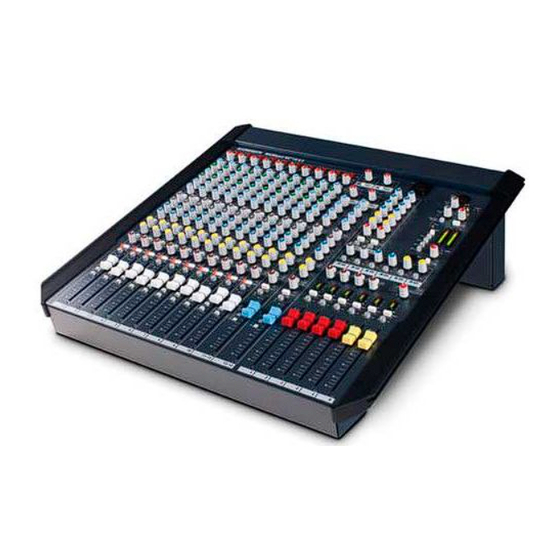
WZ 14:4:2
SYS-LINK
EXPANDER OPTION
This option connects a MixWizard WZ14:4:2 as a channel expander to a second
A&H console already fitted with SYS-LINK with just one or two interconnecting
cables.
Kit Part No:
Single option to install SYS-LINK to one MixWizard WZ14:4:2 unit to allow
interconnection to a second console already fitted with SYS-LINK.
Interconnecting cables not supplied.
For information on using SYS-LINK please refer to APPLICATIONS NOTE AP3221
FITTING INSTRUCTIONS
Publication AP3220
MixWizard
Series
WZ1442-SL1
Issue 1 Jan 98
Advertisement

Related Manuals for ALLEN & HEATH MixWizard Series


Summary of Contents for ALLEN & HEATH MixWizard Series
-
Page 1: Fitting Instructions
MixWizard Series WZ 14:4:2 SYS-LINK EXPANDER OPTION This option connects a MixWizard WZ14:4:2 as a channel expander to a second A&H console already fitted with SYS-LINK with just one or two interconnecting cables. Kit Part No: WZ1442-SL1 Single option to install SYS-LINK to one MixWizard WZ14:4:2 unit to allow interconnection to a second console already fitted with SYS-LINK. -
Page 2: Tools Required
FITTING THE SYS-LINK EXPANDER OPTION Œ CHECK THE CONTENTS : Please carefully check the SYS-LINK circuit board assembly is the correct one for the console in which it is to be installed. D type connector fixings already fitted. 4 x AB2189 Ribbon A Ribbon B INPUT... - Page 3 Ž REMOVING THE REAR COVERS Before beginning any service work, remove all power to the unit and disconnect any signal cables where necessary. The rotating connector module must be set for desk top operation to gain access to the cover. Ensure adequate lighting and use the correct tools.
- Page 4 • FITTING THE SYS-LINK CIRCUIT BOARD ASSEMBLY Locate Stereo input 13-14 circuit board assembly and Group 1 circuit board assembly. Cut the TC buss wires 5mm from the component side of the Stereo input circuit board assembly and bend the TC buss wires vertically. Slide the SYS-LINK circuit board in between the Stereo input channel and Group 1circuit board assemblies.
- Page 5 fig. 5 ALLEN & HEATH MIXWIZARD WZ14:4:2 SYS-LINK OPTION...
- Page 6 ’ SOLDERING THE SYS-LINK CIRCUIT BOARD ASSEMBLY: Bend the cut vertical TC buss wires back down and resolder them. Buss wires SYS-LINK circuit board Lift the SYS-LINK circuit board assembly and locate the TC buss wires into the slots on the circuit board. Make sure the SYS-LINK circuit board assembly is located centrally between the Stereo input circuit board and the Group circuit board assemblies.
- Page 7 “ FITTING THE SYS-LINK CONNECTORS TO THE REAR PANEL To fit the two SYS-LINK D type connectors to the rear panel of the connector module it will be necessary to partially remove the the connector circuit board assembly from the rear panel. Working from the rear of the console remove screws (A) fixing the XLR and phono connectors to the panel and using a 12mm Nutdriver or pliers, remove jack nuts (B).
- Page 8 Refering to fig. 1 & fig. 9, remove the two screws fixing the blanking panel in place and fit the two SYS-LINK connectors. Check the connectors are fitted into the correct holes. Ribbon B Ribbon A OUTPUT INPUT fig. 9 Refering to fig.
- Page 9 When all installation work is complete, remove all debris such as solder, component legs and wire clippings from inside the console and check your work carefully before reassembly. ” REFIT THE BASE : fig. 11 Refit the base and connector cover, taking care not to pinch or damage the flat flexible cables. Turn the console the correct way up.
Need help?
Do you have a question about the MixWizard Series and is the answer not in the manual?
Questions and answers