
Summary of Contents for Apollo NAPOLI SDNA-4876CG-CH
- Page 1 INSTALLATION INSTRUCTIONS NAPOLI SHOWER SDNA-4876CG-CH & SDNA-4876CG-BN TDNA-6066CG-CH & TDNA-6066CG-BN SDNA-6076CG-CH & SDNA-6076CG-BN CH - Chrome BN - Brushed Nickel...
- Page 2 Inspect the product immediately upon receipt for transit damage, missing packs/parts or manufacturing fault. Damage reported later will not be accepted. Handle the product with care avoiding knocks and shock loading to all sides and edges of the glass. Read these instructions carefully before start of installation. Special care should be taken when drilling walls to avoid hidden pipes or electrical cables.
- Page 3 IMPORTANT INFORMATION REGARDING THE INSTALLATION OF THIS SHOWER DOOR PANEL DOOR Right hand door installation shown as an example Guide Rail Brackets must be firmly Roller Guards must be postioned and attached to the wall. Installation into a secured within 1/16” of Upper Guide Rail stud is strongly recommended.
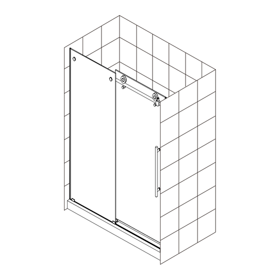
- Page 4 Detailed Diagram of shower door components...
- Page 5 Detailed Diagram of shower door components Parts List Item Item Running Rail Bottom Glass Clip Wall Brackets 2pcs Bottom Guide Anti Jump Knobs 2pcs Threshold Allen Wrench: Roller 2pcs 5pcs 2.5mm 3mm 4mm 5mm 6mm 2pcs Bump Stopper x1 for each 2pcs Glass Fixing Piece 2pcs...
- Page 6 CUT THE LENGTH OF THE THRESHOLD TOP VIEW FORMULA FINISHED WALL TO FINISHED WALL THRESHOLD = FINISHED WALL TO FINISHED WALL CALCULATE THE LENGTH OF THE RUNNING RAIL REQUIRED USING THE FORMULA PROVIDED FORMULA RUNNING RAIL = SUBTRACT 1" (24mm) FROM THE TOP VIEW OPENING BETWEEN FNISHED WALLS glass bracket...
- Page 7 RUNNING RAIL Step 3A Position the bump stoppers (5) on the bar (1) as illustrated. Secure them temporarily in place. Step 3B Position the wall brackets (2) on the running rail (1) as illustrated. Secure them temporarily in place.
- Page 8 GLASS HOLDERS Step 4A Fasten the running rail (1) to the fixed panel (21) with the glass fixing piece (6). Secure them temporarily in place. Ensure that the running rail (1) is at the highest possible position in reference to the holes of the fixed panel (21).
- Page 9 INSTALL THE BOTTOM DOOR GASKET ON THE DOOR PANEL PLACE THE PANEL ON CARBOARD BOX TO INSTALL THE BOTTOM GASKET INTERIOR SHOWER SIDE...
- Page 10 FIXED PANEL Step 7A Position the fixed panel assembly (21) on thresh old of base (B) as shown. Adjust the fixed panel (21), by way of the running rail (1), so as to force the gasket (10) against the wall. INTERIOR SHOWER SIDE The bottom guide (13) can hang off the threshold...
- Page 11 FIXED PANEL Step 8A Mark the screw locations for the wall brackets (2) on the walls on both sides of shower as well as the placement of the bottom glass clips (12) (13). Step 8B Secure glass clips (12) (13) with self-tapping screws.
- Page 12 WALL BRACKERS Step 9A Mark the screw locations on the walls on both sides of shower. Remove the running rail (1) from the wall brackets (2). Drill holes in walls until wall stud is reached with a drill bit intended for ceramic tiles. Fasten the wall brackets (2) with screws ST5x2 1/8"...
- Page 13 SLIDING DOOR Step 10A Assemble the 2 top rollers (2) to the door panel (20) as illustrated. Interior shower side Step 10B Install anti jump knobs (3), making sure that they are tangent to the running rail (1). Through the use of the crammed washers, adjust rollers so that the sliding door panel is parallel to the running rail.
- Page 14 SLIDING DOOR Step 11A Install door panel (20), ensure rollers are positioned on top of the running rail (1). Install handle (7) onto sliding door (20). Ensure that clear washers on either side of glass are installed. Ensure that the door panel (20) is placed within the bottom center guide (13). Note the placement of the bottom door gasket (9).
- Page 15 GASKETS INSTALLATION Step 12A Install door side gasket (8) onto sliding fixed panel (21). 3/4" (17.5mm) BOTTOM...
- Page 16 STOPPERS Step 13A Adjust the position of the stoppers (5) so as to ensure a maximum opening and closing range. Ensure that the sliding door gasket (10) is forced against the wall. Door closed Door open...
- Page 17 SILICONE Step 14A Apply silicone between the bottom of the fixed panel and the threshold of the base. Silicone application along the length of the threshold is also suggested. In both cases, it is done from the outside of the shower area.
Need help?
Do you have a question about the NAPOLI SDNA-4876CG-CH and is the answer not in the manual?
Questions and answers