
Related Manuals for Quantronix CUBISCAN 325


Summary of Contents for Quantronix CUBISCAN 325
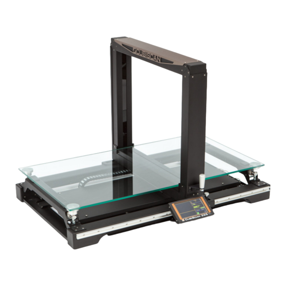
- Page 1 CUBISCAN ® Service manual Version 1.0 Quantronix, Inc. Cubing and weighing systems 380 South 200 West P.O. Box 929 Farmington, Utah 84025 U.S.A. Phone: 801.451.7000 Website: http://www.cubiscan.com...
- Page 2 Cubiscan 325 service manual Cubiscan ® and the Quantronix logo are registered trademarks of Quantronix, Inc. Scanning New Dimensions™, Qbit™, QbitWIN™, and The FreightWeigh System™ are trademarks of Quantronix, Inc. ® Windows is a registered trademark of Microsoft Corporation. Cubiscan ® software and firmware are protected by international and domestic copyrights.
- Page 3 Limited warranty Quantronix new product Statement of Warranty. Quantronix, Inc.’s, warranty obligations are limited to the terms set forth below: Quantronix (hereinafter referred to as the “Seller”) warrants that its new product is in accordance with Seller’s published specifications (or those agreed upon with Buyer in writing) at the time of sale or lease and that it is free from non- cosmetic defects in materials and workmanship under normal use for a period of one (1) year from the date of sale or the commencement date under a written equipment lease or rental agreement (the “Warranty Period”).
- Page 4 8.Not been manufactured by Seller including parts, accessories, or components which have been integrated into, used alongside of, or in conjunction with a product manufactured by Seller. TO THE EXTENT PERMITTED BY LAW, THIS WARRANTY AND THE REMEDIES SET FORTH ABOVE ARE EXCLUSIVE AND IN LIEU OF ALL OTHER WARRANTIES, REMEDIES AND CONDITIONS, WHETHER ORAL OR WRITTEN, STATUTORY, EXPRESS OR IMPLIED.
-
Page 5: Table Of Contents
TABLE OF CONTENTS CHAPTER 1 DIAGNOSTICS ........1 Booting process errors . - Page 6 USB port cable pin assignments ......50 Cubiscan 325 command set ....... . 51 Command set summary .
- Page 7 Reset system ......... 64 Save parameters .
- Page 8 Cubiscan 325 parts ........
- Page 9 Figure 31 Power cables ............30 Figure 32 Width receiver gate cover .
- Page 10 Figure 65 Inside load cell summing box ......... 43 Figure 66 Cut view .
-
Page 11: Diagnostics
CHAPTER 1 DIAGNOSTICS This section describes the diagnostics procedures for the Cubiscan 325. This chapter is divided into the following sections: –“Booting process errors” on page 2 –“Dimensional errors” on page 4 –“Gate movement errors” on page 8 –“Miscellaneous errors” on page 10 –“Scale errors”... -
Page 12: Booting Process Errors
Cubiscan Technical Assistance at 801.451.7000. Reading gate This process may be delayed and read DONE instead of PASS if the Cubiscan 325 fails to detect gate board(s). Complete the following steps if the reading gate process reads DONE. 1. Make sure that the gate power cable is securely connected. -
Page 13: Failure To Turn On
4. Contact your IT support. Failure to turn on Complete the following steps if the Cubiscan 325 fails to turn on when the power switch is turned to the On position. 1. Is the power cable connected to both the Cubiscan 325 and a working outlet? If the Cubiscan 325 is mobile, is the portable power supply turned on? 2. -
Page 14: Dimensional Errors
Inconsistent measurement readings Complete the following steps if you are receiving inconsistent measurement readings. 1. Make sure that the object you are measuring is not clear or transparent. The Cubiscan 325 can only measure objects that are opaque. 2. Does the object you are measuring have a rigid shape? If the object that you are measuring does not have a rigid, stable shape (such as clothing) then it is able to change shape. -
Page 15: Item Exceeds Boundary
Cubiscan 325 finds the top and bottom limits and automatically picks the best values. Move the gate to the middle of the Cubiscan 325 and then tap ALL. Make sure the platform is empty of all objects. This test will take several minutes. Do not touch the gate during this test. -
Page 16: Invalid Yellow Shapes In Measurement Results
5. Does the object you are measuring exceed or not meet the measurement range? The measurement range for the Cubiscan 325 is 0.10 in (0.2 cm) to 36.00 x 24.00 x 24.0 0 in (90.0 x 60.0 x 60.0 cm). - Page 17 LED’s are not working. Do not run the masking test if a large amount of yellow is displayed on the LED beam bars. If too many LED’s are masked, the Cubiscan 325 will not be able to measure objects. To run the masking test, start with the gate in the home position (right side) and slowly move it all the way to the left, and back into the home position.
-
Page 18: Gate Movement Errors
DIAGNOSTICS Gate movement errors Gate movement errors This section describes the various gate movement errors that can occur with the Cubiscan 325. Refer to the following sections for more information. Gate cursor not moving Complete the following steps if the green gate cursor does not follow the gate’s movements. -
Page 19: Gate Speed Warning
3. Check the green encoder light. If this light is out, the cable may be loose or disconnected. Check the cable and make sure it is securely connected at both ends. If the light still does not light, the encoder may need to be replaced. If the Cubiscan 325 is off this light will also be off. -
Page 20: Miscellaneous Errors
Frozen or not functioning Complete the following steps if the Cubiscan 325 is not functioning or frozen. 1. Turn the Cubiscan 325 off and allow power to drain for at least 20 seconds. Turn the Cubiscan 325 back on. 2. If cycling the power does not correct the problem, power the Cubiscan 325 off and remove the SD card. -
Page 21: Touchscreen Is Not Functioning
Complete the following steps if the touchscreen is frozen, behaving erratically, or responding poorly. 1. Reboot the Cubiscan 325. 2. Make sure the display cable is securely plugged in at both ends. 3. Is the touchscreen surface damaged? If the touchscreen is damaged, you may require a replacement part. -
Page 22: Scale Errors
Dashes in the bottom of the weight field mean that the scale is reading less than zero. If you have dashes appearing in the bottom of the weight field, complete the following steps: –Make sure that there are no fans blowing air onto the Cubiscan 325. The scale is sensitive and moving air can affect scale readings. -
Page 23: Different Load Cells Report Different Weights
If needed, adjust the bottom bolt with a wrench. 7. Make sure that there are no objects on the platform and zero the Cubiscan 325 by tapping the Zero button that is found on the main screen. If an accurate weight is not displayed in the weight field, continue on to the next step. -
Page 24: No Zero Indicator
7. Make sure that all load cell summing box cables are securely attached. 8. Zero the Cubiscan 325 by tapping the Zero button that is found on the main screen. When you zero the Cubiscan 325, make sure the platform is free of all objects. -
Page 25: Scale Calibration
CHAPTER 2 SCALE CALIBRATION To calibrate the Cubiscan 325 scale, you will need an official test weight up to 50 pounds (25 kg) (it is recommended that you calibrate with the maximum weight). IMPORTANT: Do not begin scale calibration until you have the test weight. Calibrating without an accurate known weight (within 0.01 of a lb/kg) can make all future weight readings inaccurate. -
Page 26: Figure 6 First Scale Calibration Screen
SCALE CALIBRATION Scale calibration Figure 6 First scale calibration screen 3. The following screen is displayed. Clear the scale of all objects, and tap Next to continue. Figure 7 Second scale calibration screen Cubiscan 325 Service Manual... -
Page 27: Figure 8 Calibration Weights On Scale
SCALE CALIBRATION Scale calibration 4. Place the calibration weight(s) on the Cubiscan 325 platform (roughly in the center). An example is shown below. Figure 8 Calibration weights on scale 5. Tap Next to continue. Figure 9 Scale calibration complete 6. You have finished calibrating the scale. Tap HOME to return to the home screen or if you would like to try calibrating the scale again, tap Next. -
Page 28: Cleaning
This section describes how to clean the glass platform. To clean the glass platform, remove it from the Cubiscan 325. Clean both sides of the platform thoroughly with a clean, damp cloth. You can use small amounts of glass cleaner to clean the glass if necessary, making sure that the glass cleaner does NOT come into contact with the gate filters. -
Page 29: Updating The Firmware
CHAPTER 4 UPDATING THE FIRMWARE This section describes the procedures used to update the firmware for the Cubiscan 325. There are two common methods used, updating the firmware via the SD card or a serial connection. You should use the serial connection method when the firmware or touchscreen is malfunctioning. -
Page 30: Updating Firmware Via A Serial Connection
Figure 11 correct bin file and tap Update Firmware. SD card 13. The Cubiscan 325 will take several moments to update the firmware. Do not power off the Cubiscan while the firmware is being updated, this may damage circuit boards. - Page 31 Figure 15 9. Connect one end of the RS-232 cable to the adapter Jumper 2 and the other end to the back of the Cubiscan 325 controller. 10. On your computer, open the CS125Downloader.exe. 11. Navigate to the CS125Downloader.exe folder using the Directory.
-
Page 32: Checking The Firmware Version
Checking the firmware version This section describes how to check the version of firmware that the Cubiscan 325 is using. 1. Go to MENU > About > Version. The Main field displays which version of firmware is being used. Cubiscan 325 Service Manual... -
Page 33: Balancing The Load Cells
CHAPTER 5 BALANCING THE LOAD CELLS This section describes the procedure used to balance the load cells of the Cubiscan 325. Balancing the load cells This section describes how to balance the Cubiscan 325’s load cells. Items needed –Small flathead screwdriver –5/64'' Allen wrench... -
Page 34: Figure 14 Figure
8. Place the 25 lb weight on each corner of the Cubiscan 325. Record all four values. Figure 15 shows which Cubiscan 325 corner (where the load cells are located) corresponds with each POT. 9. Choose the two corners that are closest to 25 lb. - Page 35 14. Slide the center cover back into place and tighten the thumb screws. 15. When everything has been replaced and the load cells have been balanced, you need to recalibrate the scale. For instructions on calibrating the scale, “Scale Calibration” on page Cubiscan 325 Service Manual...
-
Page 36: Part Replacement
CHAPTER 6 PART REPLACEMENT This section describes the procedures used to replace various parts of the Cubiscan 325. The parts are listed below. –“Replacing a fuse” on page 26 –“Replacing a height receiver board” on page 27 –“Replacing a height transmitter board” on page 28 –“Replacing a width transmitter board”... -
Page 37: Replacing A Height Receiver Board
PART REPLACEMENT Replacing a height receiver board 5. Shut the fuse drawer. 6. Reconnect the power cord. 7. Power the Cubiscan 325 on. Replacing a height receiver board Figure 16 This section describes how to replace the height Height receiver gate cover receiver board on the Cubiscan 325. -
Page 38: Replacing A Height Transmitter Board
11. Replace the gate cover and screw it into place. Figure 19 12. Power the Cubiscan 325 on. Jumper position 13. You now need to run a threshold test. Go to Menu > Diagnose > Gate. Move the gate to the middle of the Cubiscan and then tap ALL. -
Page 39: Replacing A Width Transmitter Board
10. Replace the gate cover and screw it into place. 11. Power the Cubiscan 325 on. 12. You now need to run a threshold test. Go to Menu > Diagnose > Gate. Move the gate to the middle of the Cubiscan and then tap ALL. - Page 40 The width transmitter boards are located at the bottom of the gate. 1. Power the Cubiscan 325 off. 2. You will need to remove the back gate cover to access this board. Remove the six screws shown in Figure 21 and then remove the gate cover.
-
Page 41: Replacing A Width Receiver Board
17. Make sure no cables are being pinched, then replace the gate cover and screw it into place. 18. Power the Cubiscan 325 on. 19. You now need to run a threshold test. Go to Menu > Diagnose > Gate. Move the gate to the middle of the Cubiscan and then tap ALL. -
Page 42: Replacing The Encoder
10. Replace the gate cover and screw it into place. 11. Power the Cubiscan 325 on. 12. You now need to run a threshold test. Go to Menu > Diagnose > Gate. Move the gate to the middle of the Cubiscan and then tap ALL. - Page 43 Encoder screws 4. Move the gate into the home position (the right side if facing the front of the Cubiscan 325). 5. We recommend trying to work around the glass platform without removing it. If it becomes a nuisance, carefully lift the platform using two people and set it aside.
-
Page 44: Replacing The Encoder Magnet Strip
Figure 34 Cable carrier latches 20. Screw the ribbon cables back into place. 21. Power the Cubiscan 325 on. 22. Move the gate slowly back and forth and make sure that everything appears to be working correctly. Make sure that no wires are being pinched and the gate has free movement. -
Page 45: Replacing The Proximity Sensor
The magnet should be roughly centered on the width of the linear guide; equal parts of the linear guide should show on each side of the encoder magnet. 5. Power the Cubiscan 325 back on. Replacing the proximity sensor Figure 36... -
Page 46: Replacing The Controller Box
–5/16'' wrench –Replacement controller box Complete the following steps to replace the controller. 1. Power the Cubiscan 325 off and disconnect the power cord. 2. Remove the two center cover thumb screws that are located on the right side of the system. - Page 47 6. Slide the controller box to the right (if you are facing the front of the Cubiscan 325) and up to remove it from the Cubiscan 325. 7. Locate the replacement controller box and place it in the Cubiscan 325 base assembly, being sure to slide the thumb screws into the slots.
-
Page 48: Replacing The Motherboard
–Replacement motherboard Remove center cover Complete the following steps to replace the motherboard. 1. Power the Cubiscan 325 off. 2. Remove the two center cover thumb screws that are located on the right side of the system. See Figure 3. Slide the center cover to the left so that you can access the controller. -
Page 49: Replacing The Power Supply
13. Slide the center cover back into place and tighten Figure 45 Motherboard cables the thumb screws. 14. Power the Cubiscan 325 on. Replacing the power supply This section describes how to replace the power supply. The power supply is located in the controller box. - Page 50 Figure 50 Power supply cables 16. Reconnect the power supply cables. 17. Replace the cage lid and screw it into place. 18. Replace the motherboard and screw it into place. 19. Reconnect the motherboard cables. Cubiscan 325 Service Manual...
-
Page 51: Replacing The Scale Card
Replacing the scale card 20. Replace the controller box lid and screw it into place. 21. Slide the center cover back into place and tighten the thumb screws. 22. Power the Cubiscan 325 on. Screw Figure 51 Power supply cage screw Replacing the scale card This section describes how to replace the scale card. - Page 52 Load cell summing board Scale card 14. Power the Cubiscan 325 on. Figure 55 15. Calibrate the Cubiscan 325 scale. For instructions on Side view of load cell summing box calibrating the scale, see “Scale Calibration” on page Screws...
-
Page 53: Replacing The Load Cell Summing Board
–Phillips screwdriver –Replacement load cell summing board Complete the following steps to replace the load cell summing board. 1. Power the Cubiscan 325 off. Figure 58 Load cell summing box 2. Remove the two center cover thumb screws that are located on the right side of the system. -
Page 54: Replacing A Load Cell
Figure 63 Wires drawing Replacing a load cell This section describes how to replace a load cell. The Cubiscan 325 has four load cells, located in each corner. Items needed –5/64'' Allen wrench –Small, short flathead screwdriver –7/16'' wrench (2) –17/32'' wrench... - Page 55 PART REPLACEMENT Replacing a load cell Complete the following steps to replace a load cell. 1. Power the Cubiscan 325 off. 2. Using two people, remove the glass platform and set it aside. 3. Remove the two center cover thumb screws that are located on the right side of the system.
- Page 56 Load cell and ball cup holder 23. Completely tighten the bolts that hold the load cell in place. 24. Power the Cubiscan 325 on. 25. When you have finished replacing the load cell you will need to balance the load cells. For instructions on balancing the load cells, see “Balancing the Load...
-
Page 57: Replacing/Adjusting Carriage Assemblies
The carriage assemblies are the wheels that allow linear gate movement. There are two types of carriage assemblies and linear guides on the Cubiscan 325. The back linear Figure 73 Screws securing wheel set guide is an open rail that uses two three-wheel carriage assemblies. -
Page 58: Appendix Acommunications Protocol
This appendix contains the cable pin assignments and command set description for the interface between the Cubiscan 325 and a host computer via a serial RS-232 connection, a USB connection, as well as for the interface between the Cubiscan 325 and a network via an Ethernet TCP/IP connection. -
Page 59: Ethernet (Tcp/Ip) Cable Pin Assignments
None Data Bits Start Bits Stop Bits Ethernet (TCP/IP) cable pin assignments The Cubiscan 325 Ethernet port uses the 10/100Base-T TCP/IP communications protocol. The following table shows the Ethernet RJ-45 connector pin assignments. RJ-45 connector pin assignments Signal Description Transmit Data... -
Page 60: Usb Port Cable Pin Assignments
RS-232 communications line and the computer operating system. This makes the USB device appear as a traditional RS-232 port. The Cubiscan 325 command set can be sent, via USB, using RS-232 communication software. CubiScan 325 Service Manual... -
Page 61: Cubiscan 325 Command Set
Cubiscan 325 command set This section describes the commands recognized by the Cubiscan 325 to cube and weigh objects and to set up the Cubiscan 325 for cubing and weighing (dimension units, factor toggle, calibration, and so on). All command packets begin with a STX (start of text) and end with an ETX (end of text), CR (carriage return), and LF (line feed). -
Page 62: Command Set Summary
COMMUNICATIONS PROTOCOL Cubiscan 325 command set Command set summary The Cubiscan 325 recognizes the following commands from the command set for a serial, USB, or Ethernet connection. The table below shows the Command Set Summary. (A) - Command Character (B) - Command Hex Value(s) -
Page 63: Build Number
(LF) Cubiscan 100 compatible measure mode This data packet is received from the Cubiscan 325 when a gate measurement is completed. It is backwards compatible with the Cubiscan 100. The Cubiscan must be manually set to Cubiscan 100 compatibility mode. - Page 64 COMMUNICATIONS PROTOCOL Cubiscan 325 command set Pos Len Description Type Range ASCII Carriage return Control (CR) Line feed Control (LF) Acknowledge format Start of text Control (STX) Measure command Alpha Acknowledge Alpha Cubiscan/Host Alpha (C/H) 43h or 48h originated City code...
-
Page 65: Dimension Units
COMMUNICATIONS PROTOCOL Cubiscan 325 command set Pos Len Description Type Range ASCII Line feed Control (LF) Negative acknowledge format Start of text Control (STX) Measure command Alpha Neg. acknowledge Alpha Cubiscan/Host Alpha (C/H) 43h or 48h originated Corner sensor/Measure/ Alpha... -
Page 66: Emitter Toggle
End of text Control (ETX) Carriage return Control (CR) Line feed Control (LF) Emitter toggle This command causes the Cubiscan 325 to turn On/Off the gate emitters. Pos Len Description Type Range ASCII Command format Start of text Control (STX) -
Page 67: Factor Table
Cubiscan 325 command set Factor table This command causes the Cubiscan 325 to store new dimensional weight factors. There are eight factors used, depending on the current shipping mode (international or domestic), dimension unit (in or cm), and weight unit (lb or kg). -
Page 68: Factor Toggle
COMMUNICATIONS PROTOCOL Cubiscan 325 command set Pos Len Description Type Range ASCII Line feed Control (LF) Negative acknowledge format Start of text Control (STX) Factor table command Alpha Neg. acknowledge Alpha End of text Control (ETX) Carriage return Control (CR) -
Page 69: Flash Firmware
COMMUNICATIONS PROTOCOL Cubiscan 325 command set Flash firmware This command causes the Cubiscan 325 to flash file cs125.bin stored on the SD card. Pos Len Description Type Range ASCII Command format Start of text Control (STX) Flash command Alpha End of text... - Page 70 COMMUNICATIONS PROTOCOL Cubiscan 325 command set Pos Len Description Type Range ASCII Cubiscan/Host Alpha (C/H) 43h or 48h originated Location identifier Alpha 000000-ZZZZZZ Comma Alpha Length identifier Alpha Length Numeric 00.00 - 99.99 Comma Alpha Width identifier Alpha Width Numeric 00.00 - 99.99...
-
Page 71: Identification/Serial Number
Control (CR) Line feed Control (LF) Identification/Serial number This command causes the Cubiscan 325 to change its current serial number data field. The serial number is an eight-digit code which uniquely identifies the Cubiscan 325. Pos Len Description Type Range... -
Page 72: Key Coordinates
COMMUNICATIONS PROTOCOL Cubiscan 325 command set Key coordinates This command causes the Cubiscan 325 to accept keyboard input in touch pad coordinates. The X coordinate is horizontal, the Y coordinate is vertical. Pos Len Description Type Range ASCII Command format... -
Page 73: Location Identification
This command is used to set the Cubiscan 325 location identification. The location identification is a six-digit code which uniquely identifies the Cubiscan 325 within the user’s operation. This location identification is included in each measurement packet. This data is stored in permanent memory and need only be set once for each Cubiscan 325. -
Page 74: Reset System
Alpha End of text Control (ETX) Carriage return Control (CR) Line feed Control (LF) Reset system This command causes the Cubiscan 325 to reboot. Pos Len Description Type Range ASCII Command format Start of text Control (STX) Reset command Alpha... -
Page 75: Save Parameters
(ETX) Carriage return Control (CR) Line feed Control (LF) Save parameters This command causes the Cubiscan 325 to save all current parameters to the file param125.txt on the SD card. Pos Len Description Type Range ASCII Command format Start of text... -
Page 76: Scale Calibration
This function is required when the load cell is replaced, when a new controller is installed, or for routine calibration. This command causes the Cubiscan 325 to reply with a scale calibration code. Each time this command is sent, the instrument prompts the operator to follow a defined calibration pattern. -
Page 77: Scale Reading
COMMUNICATIONS PROTOCOL Cubiscan 325 command set Scale reading This command causes the Cubiscan 325 to report the measured weight of objects on the scale. This can be used to verify if the scale is empty. Pos Len Description Type Range... -
Page 78: Scrape Screen
(ETX) Carriage return Control (CR) Line feed Control (LF) Serial get This command causes the Cubiscan 325 to transfer a file from the virtual file system via RS-232 or USB packets. Pos Len Description Type Range ASCII Command format Start of text... -
Page 79: Serial Loop Back
Control (ETX) Carriage return Control (CR) Line feed Control (LF) Serial loop back This command causes the Cubiscan 325 to report a command code to the display. Pos Len Description Type Range ASCII Command format Start of text Control (STX) -
Page 80: Serial Put
COMMUNICATIONS PROTOCOL Cubiscan 325 command set Pos Len Description Type Range ASCII Loop back command Alpha Acknowledge Alpha End of text Control (ETX) Carriage return Control (CR) Line feed Control (LF) Negative acknowledge format Start of text Control (STX) Loop back command Alpha Neg. -
Page 81: Smallest Box Mode
Control (ETX) Carriage return Control (CR) Line feed Control (LF) Smallest box mode This command causes the Cubiscan 325 to calculate measurements based on the smallest box. Pos Len Description Type Range ASCII Command format Start of text Control (STX) -
Page 82: Test
(LF) Test This command causes the Cubiscan 325 to reply with an error code. A response of TA00 means that the Cubiscan 325 is ready and responding to transmissions from the host. If the host receives no response from the control unit after sending this command, an error condition exists in the communications between the host and controller. -
Page 83: Units
COMMUNICATIONS PROTOCOL Cubiscan 325 command set Units This command causes the Cubiscan 325 to report its current unit settings, dimensional factor, and location ID. Pos Len Description Type Range ASCII Command format Start of text Control (STX) Values command Alpha... -
Page 84: Values
COMMUNICATIONS PROTOCOL Cubiscan 325 command set Values This command causes the Cubiscan 325 to report various internal parameters. This is useful for troubleshooting. Pos Len Description Type Range ASCII Command format Start of text Control (STX) Values command Alpha End of text... - Page 85 COMMUNICATIONS PROTOCOL Cubiscan 325 command set Pos Len Description Type Range ASCII Height gain Numeric 00.0-99.9 Comma Alpha Length pulses Numeric 00-99 Comma Alpha Width pulses Numeric 00-99 Comma Alpha Height pulses Numeric 00-99 Comma Alpha Length wait time Numeric...
-
Page 86: Weight Units
Carriage return Control (CR) Line feed Control (LF) Zero This command should be issued periodically to force the Cubiscan 325 to perform internal compensations to adjust to changes in temperature and humidity. This command should only be CubiScan 325 Service Manual... -
Page 87: Tcp/Ip Communications Setup Command Set
(LF) TCP/IP communications setup command set This section describes the commands recognized by the Cubiscan 325 to set up the Cubiscan 325 for communications with a network using the TCP/IP protocol. You can use the Qbit, QbitTCP software to configure the Cubiscan 325 for TCP/IP communications. -
Page 88: Tcp/Ip Command Set Summary
40h+50h “Set port” 7Eh+50h “Read subnet address” 40h+4Eh “Set subnet address” 7Eh+4Eh Read gateway address This command is used to read the current gateway address setting from the Cubiscan 325. Description Type Range ASCII Command format Start of text Control... -
Page 89: Set Gateway Address
(LF) Set gateway address This command is used to set the network gateway address on the Cubiscan 325. It can be the address of a network server or router and is expressed in “dot” notation. Consult your network administrator to obtain the network gateway address. -
Page 90: Read Ip Address
Control (ETX) Carriage return Control (CR) Line feed Control (LF) Read IP address This command is used to read the current IP address setting from the Cubiscan 325. Description Type Range ASCII Command format Start of text Control (STX) Read command... -
Page 91: Set Ip Address
(LF) Set IP address This command is used to set the Cubiscan 325 IP address. The IP address, or Internet address, is usually expressed in “dot” notation; for example, “121.43.6.234.” The first three groups of numbers (e.g., 121.43.6) are usually specific to the network to which you are connecting. The last number (e.g., 234) is specific to a particular Cubiscan 325. -
Page 92: Read Mac Address
Range ASCII Carriage return Control (CR) Line feed Control (LF) Read MAC address This command is used to read the current MAC address setting from the Cubiscan 325. Description Type Range ASCII Command format Start of text Control (STX) Read command... -
Page 93: Set Mac Address
COMMUNICATIONS PROTOCOL TCP/IP communications setup command set Set MAC address This command is used to set the MAC address on the Cubiscan 325. Description Type Range ASCII Command format Start of text Control (STX) Set command Alpha MAC address command... -
Page 94: Read Port
49151 are “registered ports” listed by the IANA, and can be used by ordinary user processes on most systems. Ports 49152 through 65535 are called “dynamic and/or private ports” and are free for use. It is recommended that the Cubiscan 325 TCP port be set to a CubiScan 325 Service Manual... -
Page 95: Read Subnet Address
Control (ETX) Carriage return Control (CR) Line feed Control (LF) Read subnet address This command is used to read the current subnet address setting from the Cubiscan 325. Description Type Range ASCII Command format Start of text Control (STX) Read command... -
Page 96: Set Subnet Address
(LF) Set subnet address This command is used to set the Cubiscan 325 subnet address. The subnet (sub-network) is a separate part of an organization’s network. A subnet address tells the network’s router where on the network to send incoming packets of information. - Page 97 (CR) Line feed Control (LF) Negative acknowledge format Start of text Control (STX) Set command Alpha Subnet address command Alpha Neg. acknowledge Alpha End of text Control (ETX) Carriage return Control (CR) Line feed Control (LF) CubiScan 325 Service Manual...
-
Page 98: Appendix Bparts List
APPENDIX B PARTS LIST Following is a list of parts that can be purchased for the Cubiscan 325 as spare parts or if replacement is necessary. Part No. Description Quantity/Unit 10083 AC power cord 10558 Scale card PCB 12344 1/2'' diameter ball...
Need help?
Do you have a question about the CUBISCAN 325 and is the answer not in the manual?
Questions and answers