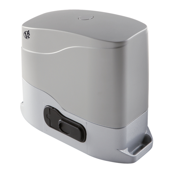
Advertisement
ATTUATORE ELETTROMECCANICO 230V / 120V IRREVERSIBILE
I
A CREMAGLIERA PER CANCELLI SCORREVOLI FINO A 600 /400 KG
230V / 120V ELECTRO-MECHANICAL IRREVERSIBLE RACK
GB
ACTUATOR FOR SLIDING GATES UP TO 600 /400 KG
OPERATEUR ELECTROMECANIQUE 230V / 120V IRREVERSIBLE A
F
CREMAILLERE POUR PORTAILS COULISSANTS JUSQU'A 600 /400 KG
MOTORREDUCTOR ELECTROMECÁNICO 230V / 120V IRREVERSIBLE
E
A CREMALLERA PARA PUERTAS CORREDERAS HASTA 600 /400KG
ACTUADOR ELECTROMECÂNICO 230V / 120V IRREVERSÍVEL PARA
P
ACCIONAR PORTÕES DE CORRER ATÉ 600 /400 KG DE PESO
ELEKTROMECHANISCHER NICHT UMKEHRBARER STELLANTRIEB
D
230V UND 120V FÜR SCHIEBETORE BIS ZU 600 /400 KG
ELEKTROMECHANISCHE, ONOMKEERBARE SCHUIFHEKMOTOR 230V
NL
EN 120V VOOR AANDRIJVING SCHUIFHEKKEN TOT EEN GEWICHT
VAN 600 /400 KG
V2 S.p.A.
Corso Principi di Piemonte, 65/67 - 12035 RACCONIGI (CN) ITALY
tel. +39 01 72 81 24 11
fax +39 01 72 84 050
info@v2home.com
www.v2home.com
Gold400A / Gold600A
IL n. 269-1
EDIZ. 28/08/2009
Advertisement
Table of Contents

Summary of Contents for V2 Gold400A Series
- Page 1 V2 S.p.A. Corso Principi di Piemonte, 65/67 - 12035 RACCONIGI (CN) ITALY tel. +39 01 72 81 24 11 fax +39 01 72 84 050 IL n. 269-1 info@v2home.com www.v2home.com EDIZ. 28/08/2009 Gold400A / Gold600A ATTUATORE ELETTROMECCANICO 230V / 120V IRREVERSIBILE...
-
Page 2: Table Of Contents
V2 S.p.A. declares that the series of GOLD actuators are in use or wrong installation. conformity with the provisions of the following EC directives:... -
Page 3: Technical Specifications
TECHNICAL GOLD600A-230V GOLD600A-120V GOLD400A-230V GOLD400A-120V SPECIFICATIONS GOLD600AM-230V GOLD600AM-120V GOLD400AM-230V GOLD400AM-120V Gate maximum weight 600 Kg 600 Kg 400 Kg 400 Kg Power supply 230V / 50Hz 120V / 60Hz 230V / 50Hz 120V / 60Hz Maximum power 500 W 500 W 350 W 350 W Idling current... -
Page 4: Preparatory Steps
PREPARATORY STEPS WARNING: insert the gasket in the hole through which the cables pass, as shown in the picture. Pierce the gasket in order to CAREFULLY OBSERVE EUROPEAN REGULATIONS EN12445 AND let pass the cables to be connected to the central unit, being EN12453 (WHICH REPLACE UNI 8612). -
Page 5: Installing The Limit Switches
INSTALLING THE MAGNETIC LIMIT SWITCHES Install the supplied magnet holder on the rack in a way that, in the opening and closing limit positions, the magnet be positioned next to the magnetic sensor behind the hood (as near as possible to the hood). The supplied magnets have been colored differently in order to be distinguished from each other: RED MAGNET CLOSING LIMIT SWITCH... -
Page 6: Motor Overriding System
MOTOR OVERRIDING SYSTEM WARNING: In case the leaf overruns its final position and In case of a blackout, the gate can be operated directly from the motor. Insert the key supplied in the lock 1 on the front side of impacts against the safety stroke end (i.e. -
Page 7: Control Unit
The PRGS2 control unit is an innovative V2 product guaranteeing safety and reliability for sliding gate automation. The photocell can be used with two settings: 1. - Page 8 STOP Conductive rubber edge: connect the edge cables between terminals L7 and L8 on the control unit. The STOP input is intended for devices with the switch normally closed. The STOP command causes the immediate stop of the gate. A subsequent START command activates the gate in the opposite direction of movement.
- Page 9 ELECTRICAL CONNECTION TABLE CAUTION: CAUTION: If not used, the normally closed inputs (STOP, PHOTO, The connection between the control unit and the motor EDGE) must be jumpered with the commands common line must be made according to the motor position in respect to COM (-) the gate.
- Page 10 CONTROL UNIT INDICATORS Antenna (LEDS) Antenna shield The highlighted boxes indicate the state of the LEDs when the Opening command for a standard connection gate is resting. device with switch normally open. Pedestrian opening command for a standard connection device with switch normally open. START START input closed START input open...
- Page 11 PROGRAMMING THE OPERATIONAL LOGIC It is possible for the control unit to use several different operational logic states, by simply moving the dip-switches located on the card. The functions associated with each individual dip-switch are listed below. FUNCTION SETTING DESCRIPTION Disabled The blinker is switched on when the motor is started Pre-flashing...


Need help?
Do you have a question about the Gold400A Series and is the answer not in the manual?
Questions and answers