
Summary of Contents for Fire Com 3010R Series
- Page 1 • 3020R 3010R FIRE APPARATUS INTERCOM SYSTEM 3020R INTERCOM 3020R REMOTE HEAD I N S T A L L A T I O N & O P E R A T I O N M A N U A L...
-
Page 3: Table Of Contents
3010R Series Intercoms ........ -
Page 4: System Orientation
The result is clear, crisp on-board communication like never before. There are 2 models of intercoms in the Firecom 3010R Series. Figure 1 shows the front of the 2 different models and describes the differences between the different models. -
Page 5: System Overview
Figure 2 shows a typical system. Refer to this diagram for each component. INTERCOM The main control unit for the 3010R Series Intercom System which contains all the controls and interface circuitry. 2-WAY RADIO The existing 2-way radio in the apparatus. -
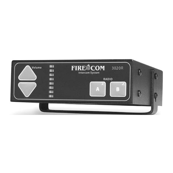
Page 6: 3010R Series Front Panel
S Y S T E M O R I E N T A T I O N 3010R SERIES FRONT PANEL Figure 3 shows the Front Panel of the 3010R and the 3020R Intercom. Listed below are the different items on the Front Panel and what they control/signify. These controls are explained further in “Intercom Operation”... -
Page 7: 3010R Series Rear Panel
S Y S T E M O R I E N T A T I O N 3010R SERIES REAR PANEL Figure 4 shows the Rear Panel of the 3020R Intercom. This section describes the different connectors located on the rear of the intercom. -
Page 8: Definitions
Any one of the six modular jacks under INTERCOM on the INTERCOM PORT: rear of the Intercom. Any model 3010R Series Intercom. INTERCOM UNIT: A round, metal, water resistant module with a single jack for PP-20: headset connection. For use on the exterior of the vehicle. -
Page 9: Pre-Installation
System Orientation (page 1) and Installation (page 12) BEFORE installing the 3010R Series Intercom onto the apparatus. Taking a little time to plan the installation BEFORE installing the 3010R Series Intercom System may prevent many installation errors which could result in improper system IMPORTANT operation. -
Page 10: Headset Modules
P R E - I N S T A L L A T I O N HEADSET MODULES There are 2 different types of Headset Modules for the 3010R Series Intercom system (Figure 5). The HM-10 is the standard module and is designed for use inside the apparatus where it is protected from the elements. -
Page 11: Daisy-Chaining The Headset Modules
P R E - I N S T A L L A T I O N DAISY-CHAINING THE HEADSET MODULES Daisy-Chaining the Headset Modules is a method used to increase the number of headset positions available, or a method of reducing the number of cable runs and the length of the cable runs. -
Page 12: Routing The Ca Cables
P R E - I N S T A L L A T I O N ROUTING THE CA CABLES The path along which you intend to run the CA Cables from the Intercom to the Headset Modules should also be planned BEFORE the installation. The items below are some of the items to consider when planning where to route the CA Cables. -
Page 13: Intercom Connections
The 3010R Series Intercom requires at least +12 volts DC nominal (with a negative ground) at .5 amps. This Intercom will accept DC voltage as high as 36 volts. The 3010R Series Intercom comes with a Power Cable Assembly and a 1.0 amp, in-line fuse. We suggest connecting the Intercom power and ground to the apparatus power buses. -
Page 14: Intercom Adjustments
16 in this manual. These adjustments to the intercom MUST be performed by a Qualified Radio Technician to ensure proper operation of the 2-way radio and 3010R Series Intercom System. IMPORTANT OPTIONAL FOOT SWITCH The optional Foot Switch (FS-1) is used in situations where the user cannot, or does not wish to, use the headset mounted Push-T o-Talk (PTT). -
Page 15: Installation
I N S T A L L A T I O N BEFORE INSTALLING the Firecom 3010R Series Intercom, make sure you have read AND UNDERSTOOD the ENTIRE installation procedure. You should also read the sections on IMPORTANT Pre-Installation (page 6) and System Orientation (page 1). If any item in the Installation... -
Page 16: Installing The Ca Cables
I N S T A L L A T I O N INSTALLING THE CA CABLES Slide a Bend-Relief Grommet over one end of the flat CA Cable, small end first. Attach a RJ-12 Modular Plug to the end of the flat CA Cable (see page 28 for instructions if necessary). -
Page 17: Power & Ground Connections
21. Connect the red wire (from pin 2) to one end of the supplied in-line fuse holder. 22. Connect the other end of the fuse holder to the vehicle's switched positive power supply. The 3010R Series Intercom System is installed and ready for connection to the radio. FIGURE 15: Power Cable Assembly... -
Page 18: Radio Connections
I N S T A L L A T I O N RADIO CONNECTIONS To ensure proper operation, the connection to the radio should be performed by a Qualified Radio Technician. IMPORTANT 23. If you are using a radio-specific interface cable, follow the directions included with the interface cable, then proceed with step 27 in this Installation Procedure. -
Page 19: Intercom Adjustments
A change to the radio programming may also be needed. The Firecom 3010R Series Intercoms have an adjustable delay between pressing the Push-To-Talk on the headset and the keying of the radio. -
Page 20: Auxiliary Input & Output
AUXILIARY INPUT & OUTPUT On the back of the 3010R Series Intercom, there are 2 jacks labeled “Aux In” and “Aux Out” (Figure 19). These jacks are 3.5 mm stereo (conductor) jacks. If a mono plug is inserted in this jack, it may damage the auxiliary device. -
Page 21: Installing The Remote Head
I N S T A L L A T I O N INSTALLING THE REMOTE HEAD One or two Remote Heads can be connected to the main base unit. The connections at the rear of the unit are identical in function. CA Cables of the style and pin-outs as the audio CA Cables will work to mount the remotes. - Page 22 I N S T A L L A T I O N 40. When mounting the Remote Head using the brackets, first plug in and thread the cable through the bracket assembly as shown in (Figure. 21). 41. Plug the CA Cable into the Remote Head and secure the panel with (4) machine screws and nuts to the front of the bracket.
-
Page 23: System Test
S Y S T E M T E S T This procedure tests all functions of the 3010R Series Intercom System and should be used to test the system for proper operation after installation. In the event of a system failure, it may also be used to help identify and isolate the exact symptoms before troubleshooting a prob- lem, and to test the system after repair work has been performed. - Page 24 S Y S T E M T E S T 11. Adjust the headset volume for a comfortable listening level. 12. Monitor radio communications. Verify that the incoming radio transmissions are the same volume as the intercom volume. 13. Repeat steps 4 to 12 for each headset/headset position on the apparatus. TEST RADIO COMMUNICATION Steps 14 to 16 are for Radio-Transmit Headsets only! These are the models FH-10 and UH-10, and have a red PTT on the ear dome.
-
Page 25: Intercom Operation
The mic is always active for intercom communications. Radio-T ransmit Headsets are typically used at the Driver , Officer and Pump Panel positions. There are 4 models of Radio-T ransmit Headsets available for use with the 3010R Series Intercom System: the UH-10, UH-10S, FH-10 and the FH-10S. There is a RED Push-To- Talk (PTT) button located on the ear dome which allows communication on the radio. - Page 26 I N T E R C O M O P E R A T I O N INTERCOM-ONLY HEADSETS The Intercom-Only Headsets receive both intercom and radio communications at all times, but are NOT radio-transmit capable. Intercom-Only Headsets are typically used at the jumpseat positions, due to the high ambient noise level at these locations (engine noise, etc.).
- Page 27 I N T E R C O M O P E R A T I O N HEADSET ADJUSTMENT The vertical fit of the headset is changed by adjusting the headband (FH models) or the headstrap (UH models). • Over-The-Head (FH) style headsets (Figure 24): These headsets have adjustable headbands with slide mechanisms located at each side above the ear domes.
-
Page 28: Volume Controls
Volume Control Buttons. IMPORTANT The Volume Controls on the 3010R Series Intercoms adjust the volume of INTERCOM COM- MUNICATION ONLY! The Volume Controls DO NOT adjust the volume of the Receive Audio from the radio(s). To adjust the volume of the Receive Audio, adjust the Receive Audio Adjustment (page 16) or the radio's volume control. -
Page 29: Radio Select Controls
I N T E R C O M O P E R A T I O N RADIO SELECT CONTROLS (3020R ONLY) The Radio Select Controls/Indicators on the 3020R ONLYcontrol which radio will be used to transmit when a PTT Button on a Radio-T ransmit Headset is pressed. They do NOT control which radio is heard in the headsets. -
Page 30: Modular Plug Installation
M O D U L A R P L U G I N S T A L L A T I O N This section describes the installation of the RJ-12 Modular Plugs onto the flat CA Cable. 1. Using the cutter blade on the crimping tool (labeled “A” in Figure 29), cut the flat CA Cable so the cut is clean and 90 degrees to the sides of the cable. -
Page 31: Troubleshooting
T R O U B L E S H O O T I N G The Firecom 3010R Series Intercom System, when installed properly and adjusted according to specifications, will perform reliably and offer you the finest in hearing protection and enhanced communication. -
Page 32: Alternator Whine & Other Distracting Noises
T R O U B L E S H O O T I N G ALTERNATOR WHINE & OTHER DISTRACTING NOISES Because of the level of ambient noise present with the apparatus motor running, alternator whine and other noises may not be noticed in the communications systems until an intercom is added. -
Page 33: Troubleshooting A Headset Location
T R O U B L E S H O O T I N G TROUBLESHOOTING A HEADSET LOCATION This procedure will help determine if a problem exists in a particular headset location, and which component in the headset location is faulty. Examine the headset’s label to determine if the headset is an Intercom-Only Headset or a Radio-Transmit Headset. -
Page 34: Advanced Troubleshooting
A D V A N C E D T R O U B L E S H O O T I N G This section is designed for use by a QUALIFIED RADIO TECHNICIAN only!!! IMPORTANT This section is designed to aid in the troubleshooting process of an intercom system that has been working properly, but has now failed. - Page 35 A D V A N C E D T R O U B L E S H O O T I N G Try swapping the intercom unit with a known good one (if one is available). If the problem persists, the problem is in the Radio or the Mobile Radio Interface wiring. If no fault can be found, then the fault must lie in the Intercom Unit.
- Page 36 A D V A N C E D T R O U B L E S H O O T I N G G) THERE IS A LOUD SQUEAL IN THE INTERCOM SYSTEM WHEN THE INTERCOM VOLUME IS TURNED UP Check for an open mic too near the speakers of a headset.
- Page 37 A D V A N C E D T R O U B L E S H O O T I N G J) THE RADIO DOESN'T KEY Check the affected headset location for faulty connections or components. See “Troubleshooting a Headset Location” (page 30). Verify proper connection of radio interface pins 3 &...
- Page 38 A D V A N C E D T R O U B L E S H O O T I N G M) ENGINE NOISE AND SIRENS ARE PRESENT IN TRANSMIT AUDIO Review the set up and operation of the intercom volume. See “Volume Controls” (page 25).
-
Page 39: Wiring Diagrams & Schematics
W I R I N G D I A G R A M S & S C H E M A T I C S 5 Conductor Plug FIGURE 32: 5 Conductor Jack HM-10 Wiring NOT USED Pin 1 Pin 6 SPEAKER HI SPEAKER LO MIC HI... -
Page 40: Pp-20 Wiring
W I R I N G D I A G R A M S & S C H E M A T I C S FIGURE 34: PP-20 Wiring 5 Conductor Jack w/GND Ring* Not Connected SPEAKER HIGH SPEAKER LO MIC HIGH MIC LOW FIGURE 35:... -
Page 41: Specifications
S P E C I F I C A T I O N S HEADSETS: Sensitivity: ....104 dB re .0002 microbar @ 1000 Hz, 1 mW Frequency Response: . -
Page 42: Options & Accessories
O P T I O N S & A C C E S S O R I E S HEADSETS: All Firecom Headsets for the 3010R Series Intercom System are equipped with a noise-can- celing electret condenser microphone on a solid, flexible boom, Glove Rugged™ plug, volume control, adjustable headstrap/headband and liquid foam ear seals. - Page 43 O P T I O N S & A C C E S S O R I E S OTHER ACCESSORIES: CLOTH COVERS: Replacement cloth covers, sold only by the dozen. Part Number: 108-0003-00 CRIMPER: Crimping tool used for installing the RJ-12 Modular Plugs onto the CA Cables (instructions included).
-
Page 44: Warranty
W A R R A N T Y TWO-YEAR LIMITED WARRANTY TO ORIGINAL PURCHASER Sonetics Corporation warrants to the original purchaser of its products, that they will be free from defects in materials and workmanship, under normal and proper use, for the period of two years from date of purchase.
Need help?
Do you have a question about the 3010R Series and is the answer not in the manual?
Questions and answers