Table of Contents
Advertisement
Quick Links
Advertisement
Table of Contents

Summary of Contents for Nextron LPM3
- Page 1 LPM3 Manual Company Nextronics Date 2018/04/16 Version LPM3-A0...
-
Page 2: Table Of Contents
INDEX 1. Introduction 1.1. Safety 1.2. Installation 1.3. Specification 2. Machine Features 2.1. Machine configuration 2.2. Function 3. Operating Instruction 3.1. Power on 3.2. Operating confirmation 3.3. Before-production confirmation 3.4. In-production confirmation 3.5. After-production confirmation 4. Software Operation Interface 4.1. User interface introduction 12~13 4.2. - Page 3 Safety precautions to avoid injury The safety measures designed by this equipment prevent operators and maintenance personnel from being harmed during the operation of the machine. The most important thing is operator or maintenance personnel must configure specific safety precautions to avoid injury.
-
Page 4: Introduction
1. Introduction This manual contains procedures for installation, safety, operation, and maintenance of a 5-ton desktop servo press-fit machine LPM3. 1.1. Safety 1. Electrical- The power wiring of three-core cable connected to the power box needs to include a grounding wire to prevent leakage currents from affecting people. -
Page 5: Installation
1.2. Installation This section describes the installation steps and requirements. 1. Notices before the installation- 1) Personnel protection requires a safety helmet and work gloves. 2) Set the security scope of the unpacking and hanging area. Except the relevant staff, other personnel are prohibited from entering. - Page 6 6. Connecting the wire- 1) Pass the power cable through the hole in the lower part of the power box of the device and strip it to lock the switch contact (above). 2) Turn on the power and measure the input of the power end of the device with an electric meter. Check if there are any power and power specifications.
-
Page 7: Specification
1.3. Machine specification label 1. Machine type, power require and weight information are labelled on the back panel of the machine. 2. Power supply: 220V AC single phase Weight: 550 kg Press-fit force: 5000 kg Press-fit distance: 80mm Machine size: 1100L x 980W x 1400H ±50mm 1400mm 3. -
Page 8: Machine Features
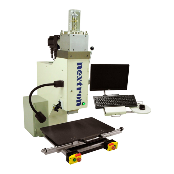
2. Machine Feature This section introduces the use, capabilities, and configuration of the LPM3 tabletop servo press-fit machine. 2.1. Machine configuration 1. C-type structure with three sides open active desktop. 2. Easily move jigs and objects to be pressed with X-Y Table. -
Page 9: Function
1. Manufacturing capability- The LPM3 can provide up to 5 tons (49,000 N) of force on the press head. The Z-axis travel is 80mm. With the standard 50mm press head, the X-Y Table surface space is up to 100mm from the upper position of press head. -
Page 10: Operating Instruction
3. Operation Instruction 3.1. Power on It is important to ensure that all safety settings are in place before power on, and that personnel maintain a distance from the machine before starting the machine. 1. Power switch- 1) The main power supply external input switch is located in the left side of the machine. Turn the switch to the OFF position (left pic.) for all input power. -
Page 11: Operating Confirmation
3.2. Operating confirmation 1. Make sure that the emergency stop switch is released. 2. Make sure that the safety handle is pulled down to the lower positioning point (below). 3. Make sure that the zero calibration job is complete. 3.3. Before-production confirmation 1. -
Page 12: Software Operation Interface
4. Software Operation Interface 4.1. User interface introduction 1. Operation- Force, distance, analysis curve, press position diagram, product data of the pressing process during production operations, production schedule and other data, production status monitoring, automatic storage and query of force curve. In addition, various error indications are linked to the operating instructions to assist in troubleshooting. -
Page 13: User Change
6. Parameter Setup- This is to set the storage path of the press recipe, drawings, statistics, graphs, and production records. The safety settings can be used to set the press force, time, standby point traversing value, PCB, connector. When the machine is set up, it is effectively protected against damage. -
Page 14: Load Recipe
3. Permission description- The permission item is related to the limitation of each function box on the homepage except the last one “Connector database” refers to the connector setting function and continuous pressing function in the edit recipe. Add - Create user name and password information, check the permission item, and press Add to add the user. Update - Click to modify the user name, click to edit the permission item, and then press Update to modify the user permissions. -
Page 15: Operation 16~19
3. Data display column - After confirming the call recipe file, the part number, creator, top press head fixture, bottom bearing fixture and PCB number will be displayed. 4. Parameter display table - After the recipe file is confirmed, the parameter values and corresponding press fixture numbers are displayed for each item set on the backplane. - Page 16 5. Time display column - Shows the instant action time of pressing (unit: sec) 6. Pressing quantity data display column - CPBPV - The total press points on the backplane Q'ty- Shows the number of completed PCB board Number of repeat - Shows the number of repeat press points 7.
- Page 17 triggering factor. Press ALARM RESET to cancel the warning and perform the OPR calibration operation. The recipe operation needs to be loaded again. 4) EMO button is triggered - After confirming that the safety condition has been eliminated, pull the EMO button and press the motor power on.
- Page 18 The press curve of the same connector will be different with the roughness of the surface of the plating layer in the terminal and PCB hole. During the pressing process, the force rises above the force upper limit is abnormal. The operation will also be stopped and a warning message will be sent out. 3) Save key - Use this key to store separately and set the path and file name in the continuous press test curve.
-
Page 19: Continue Press
4.6. Continue press Press and continue to set the job function and page description. Used for press parameter test - 1. This functional test can be used when the connector manufacturer does not provide force standard parameters for the press connector. 2. - Page 20 2) ORI_SERIES - Enter the original part number of the connector. You can also use this condition to query the database information. 3) BRANDS - Enter the brand name of the connector's maker such as Tyco、Molex、Nextron.. 4) P.S. - Enter the description of the connector.
- Page 21 5) MOD_UP #1 and #2 - Enter the number of the upper tool used by the corresponding connector. 6) MOD_DOWN #1 - Enter the number of the lower tool used by the corresponding connector. The above fields are required to input data. If you do not need to enter the fields, please enter NA. The input contents cannot have any spaces.
- Page 22 2) Sectional pressing - Check the option of sectional pressing, the window will appear sectional field, add 3 sectional point settings. According to your demand, input sectional point distance value, speed, stay time, each section indicates the following diagram. 3) Link item block - * SAVE_DATA - Set and change the changed press parameters.
-
Page 23: Edit Recipe
4.7. Edit recipe To establish recipe of the press procedure. 1. New recipe mode 1) Sequence - * Create a new file - enter the part number -> image loading -> upper fixture number -> lower fixture number -> set press position and serial number box. * Pressing parameter table - enter the total force stroke distance ->... - Page 24 blocks, which are 1, 2, 3, 4, and 5, and delete the number 3 box. The numbers of the serial numbers will form 1, 2, 3, and 4 and the original 4 becomes 3. , then 5 becomes 4. * Re-edit function - The sequence parameters of the pressing machine that have been set are reordered, and they can be sorted from 1 or any of them.
- Page 25 2. New recipe by continue press - Just like the new recipe editor, complete 1 to 6 steps first, press the 7th item and edit it to load it, match the continuous press detection data, and import the data directly for editing. Step - 1) In the continuous press function screen, press the export formula key, if it is not established in the connector database, it will be required to save it first, then enter the edit recipe page.
- Page 26 2) CONN_SERIES - Connector part number. 3) ORIGIN_SERIES - Part number of the connector manufacturer 4) BRANDS - Manufacturers of connectors such as Tyco, Molex, Nextron, 5) FORCE_STANDARD - The press force suggested by the connector manufacturer, or the force that is counted for a product, as the standard force in units (N).
-
Page 27: Process Log
4.8. Process log Description for production parameter statistics, query and quality traceability. 1. Production pressing query - 1) Enter the time period of the data to be queried in the time setting area. Use the pull-down option to set. Start date - YY(year)/MM(month)/DD(day)/hh(hour)/mm(minute)/ss(second) End date - YY(year)/MM(month)/DD(day)/hh(hour)/mm(minute)/ss(second) 2) After the time period is set, click the "REFRESH"... - Page 28 4) The item showing and setting key is to display the contents in the production record data field, as shown below. 5) After the above conditions are set and the input is completed, click on the “SEARCH” button. The production data window will appear as shown below. The data will be listed by clicking the display item. 6) Data content can be exported to .CSV format for Excel, which can be used for editing, statistics, production report or customer data.
-
Page 29: Spc
4.9. SPC The X Bar-R Chart of the yield and force of the connector production process further controls the production parameter control to achieve the best production status. 1. Yield statistics page 1) Work order press location yield statistics- * Select the drop-down list for the work order number and the PCB press location field, select the desired statistics, and then click the query. -
Page 30: Parameter Setup
4.10. Parameter setup Software normal parameter setting includes force upper and lower normal ratio values, single cycle production time, standby point shift value, data storage path, serial number (bar code) check function open..., etc. The related parameters can be adjusted according to the requirements of the textual description of the page The adjustment is completed before the setting is completed. - Page 31 3) Force setting - The unit is a percentage and set the lower limit of press force. 4) Standby position setting - In the recipe production, according to the highest point of the connector P1, increase the distance to be the standby points, so that the press head to complete a single cycle operation, standby for the next pressing position.
-
Page 32: Maintenance
5. Maintenance The following is a list of maintenance item and schedule for reference. Item By day By week By quarter By year Blowing Wipe the machine Check the wire Refuel as required Check screw Check the Z-axis ballscrew Calibrate Z-axis force sensor Warning - Turn off the main power and disconnect the power cord before and during machine maintenance. -
Page 33: Appendix
6. Appendix 6.1. Tool and accessory Item Name Function Photo Flathead To fasten or loosen screws Screwdriver C spanner To adjust the height of the press-fit machine Phillips To fasten or loosen screws Screwdriver Allen Wrench To fasten or loosen different size of screws To fasten or loosen different size of screws Adjustable Wrench and to adjust the machine's tripod for... -
Page 34: Machine Table Size
6.2. Machine table size (optional) We suggest two kinds of table size for the machine as below. The table is basically designed for operators between 155cm and 170 cm tall. Please adjust the table based on your need. Size 1-1500mmX900mmX700mm Size 2-800mmX 800mmX700mm Below drawing is for 1500mmX900mmX700mm NOTES:... -
Page 35: Contact Information
6.3. Contact information Please contact our sales window or please call us for service. Company-Nextronics Engineering Corp. Address- 2F, No. 31, Lane 169, Kang Ning Street, Hsi-chih District, New Taipei City, Taiwan Telephone-886-2-66162000 Website-www.NextronGroup.com...
Need help?
Do you have a question about the LPM3 and is the answer not in the manual?
Questions and answers