Table of Contents
Advertisement
Quick Links
Advertisement
Table of Contents

Summary of Contents for Perkin-Elmer STA 6000
- Page 1 THERMAL ANALYSIS STA 6000 Installation and Hardware Guide...
- Page 2 Release History Part Number Release Publication Date 09931394 January 2018 Any comments about the documentation for this product should be addressed to: User Assistance PerkinElmer, Inc. 710 Bridgeport Avenue Shelton, Connecticut 06484-4794 U.S.A. Or contact: http://www.perkinelmer.com/contactus/ Notices The information contained in this help file is subject to change without notice. Except as specifically set forth in its terms and conditions of sale, PerkinElmer makes no warranty of any kind with regard to this help file, including, but not limited to, the implied warranties of merchantability and fitness for a particular purpose.
-
Page 3: Table Of Contents
Select the Correct Voltage for the STA 6000 ..........38 Connect the Purge Gas Supply to the STA 6000 ...........40 Connect the Purge Gas and System Purge Gas Lines to the STA 6000 ...41 Remove the Shipping/Alignment Tool ............42 Install the Sensor ..................42 Connect the Cooling Device to the STA 6000 ..........42... - Page 4 STA 6000 Maintenance ..................60 Cleaning the Furnace and Sample Holder............ 60 Cleaning the Cover ..................60 STA 6000 Part Numbers ................... 61 AS 8000 Autosampler................63 AS 8000 Autosampler ..................64 Safety Precautions for the AS 8000 ..............66 How the AS 8000 Autosampler Works ...............
-
Page 5: Introduction
Introduction... -
Page 6: Pyris Installation
6 . STA 6000 Installation and Hardware GuideSTA 6000 Installation and Hardware Guide Pyris Installation NOTE: If you are going to install multiple analyzers, or just want to install a universal serial Install Multiple Analyzers bus, see before you begin to install an analyzer. -
Page 7: Safety And Regulatory Information
Safety and Regulatory Information... -
Page 8: Symbols Used In This Help
8 . STA 6000 Installation and Hardware GuideSTA 6000 Installation and Hardware Guide Symbols Used in this Help Bold text refers to text that is displayed on the screen. UPPERCASE text, for example ENTER or ALT, refers to keys on the computer keyboard. '+' is used to show that you have to press two keys at the same time, for example, ALT+F. - Page 9 Safety and Regulatory Information . 9 We use the term CAUTION to inform you about situations that could CAUTION result in serious damage to the instrument or other equipment. Details about these circumstances are in a box like this one. Caution (Achtung) Bedeutet, daß...
- Page 10 10 . STA 6000 Installation and Hardware GuideSTA 6000 Installation and Hardware Guide We use the term WARNING to inform you about situations that could result in personal injury to yourself or other persons. Details about these circumstances are in a box like this one.
-
Page 11: Symbols Used On The Instruments
Safety and Regulatory Information . 11 Symbols Used on the Instruments Caution, hot surface. Attention surface chaude. Caution, risk of electric shock. Attention, risque d'électrocution. Caution Documentation must be consulted to determine the nature of the potential hazard and any actions which have to be taken. -
Page 12: Electrical Warnings
12 . STA 6000 Installation and Hardware GuideSTA 6000 Installation and Hardware Guide Electrical Warnings Connect the instrument to an AC line power outlet that has a protective ground connection. To ensure satisfactory and safe operation of the instrument, it is essential that the protective ground... - Page 13 Safety and Regulatory Information . 13 Use only fuses with the required current rating and of the specified type for replacement. WARNING N'utilisez que des fusibles avec la note de courant requise et du type spécifié pour le remplacement. AVERTISSEMENT...
-
Page 14: Electromagnetic Compatibility (Emc)
14 . STA 6000 Installation and Hardware GuideSTA 6000 Installation and Hardware Guide Electromagnetic Compatibility (EMC) Europe All information concerning EMC standards is in the Declaration of Conformity, and these standards may change as the European Union adds new requirements. -
Page 15: Electrical Safety
Safety and Regulatory Information . 15 Electrical Safety This analyzer conforms to IEC publication 61010-1 (“Safety requirements for electrical equipment for measurement, control and laboratory use”) as it applies to IEC Class 1 (earthed) appliances, and therefore meets the requirements of the Low Voltage Directive 2006/95/EC. -
Page 16: Weee Instructions For Perkinelmer Products
16 . STA 6000 Installation and Hardware GuideSTA 6000 Installation and Hardware Guide WEEE Instructions for PerkinElmer Products A label with a crossed-out wheeled bin symbol and a rectangular bar indicates that the product is covered by the Waste Electrical and Electronic Equipment (WEEE) Directive and is not to be disposed of as unsorted municipal waste. - Page 17 Safety and Regulatory Information . 17...
-
Page 19: Prepare The Laboratory
Prepare the Laboratory... -
Page 20: Prepare The Laboratory
20 . STA 6000 Installation and Hardware GuideSTA 6000 Installation and Hardware Guide Prepare the Laboratory The following sections describe requirements for your Thermal Analysis System. Make sure your laboratory meets all of the requirements before you try to install the system. You should step through the topics in the order presented below. -
Page 21: Purge Gas And Pneumatic Supply
Prepare the Laboratory . 21 The instrument will operate safely between 5 °C and 40 °C. • Place the system components in an area that is not in direct sunlight or direct contact • with heating and cooling ducts or units. The instruments are for indoor use only. - Page 22 22 . STA 6000 Installation and Hardware GuideSTA 6000 Installation and Hardware Guide...
-
Page 23: Install Multiple Analyzers
Install Multiple Analyzers... -
Page 24: Install Multiple Analyzers
24 . STA 6000 Installation and Hardware GuideSTA 6000 Installation and Hardware Guide Install Multiple Analyzers The only way to attach multiple instruments to your computer is via a universal serial bus. PerkinElmer no longer supports the Multiport RS-232 Card (P/N 09402018). Installation of the universal serial bus MUST be done before installing any analyzer. - Page 25 Install Multiple Analyzers . 25 2. Attach the other end of the connector cable to the USB port on the EdgePort. EdgePort/4 EdgePort/8 DO NOT connect any instruments to the EdgePort at this time. If your computer is connected to the Internet, it will now download the software drivers for the EdgePort.
- Page 26 26 . STA 6000 Installation and Hardware GuideSTA 6000 Installation and Hardware Guide...
-
Page 27: Install An Sta 6000
Install an STA 6000... -
Page 28: Safety Precautions For The Sta 6000
The following precautions must be observed before and during use of the STA 6000: Before connecting the STA 6000 to the main outlet, check the main voltage setting and • fuse. The STA 6000 requires a good earth ground that is common to the earth ground of the • computer. •... - Page 29 AVERTISSEMENT Alw ays ensure that there is adequate ventilation w hen operating the STA 6000. Operate the STA 6000 in a fum e hood w hen running sam ples that give off tox ic gases, because the reaction gases escape through the furnace lids.
-
Page 30: Important Specifications
30 . STA 6000 Installation and Hardware GuideSTA 6000 Installation and Hardware Guide Do not exert excessive forces on the sensor disks. CAUTION Ne pas exercer de forces excessives sur les disques du capteur. ATTENTION Important Specifications Maximum power consumption... -
Page 31: Decontamination And Cleaning
Install an STA 6000 . 31 Decontamination and Cleaning Decontamination Before using any cleaning or decontamination methods except those specified by PerkinElmer, users should check with PerkinElmer that the proposed method will not damage the equipment. Customers wishing to return instrumentation and/or associated materials to PerkinElmer for repair, maintenance, warranty or trade-in purposes are advised that all returned goods must be certified as clean and free from contamination. -
Page 32: Sta 6000 Warning Labels
32 . STA 6000 Installation and Hardware GuideSTA 6000 Installation and Hardware Guide STA 6000 Warning Labels Warning Labels on the Upper Ring Around the Furnace HOT SUR FACE The furnace at the center of the ring m ay be hot. -
Page 33: Warning Labels On The Back Of The Sta 6000
Votre laboratoire doit disposer AVERTISSEMENT d'un système de ventilation fiable avant d'utiliser cet instrument. Warning Labels on the Back of the STA 6000 Alw ays keep airflow unobstructed To maintain adequate ventilation do not block the back of the instrument. - Page 34 34 . STA 6000 Installation and Hardware GuideSTA 6000 Installation and Hardware Guide For protection against fire hazard replace only w ith the sam e type and rating of fuse. WARNING P our la protection contre les risques d'incendie, rem placer uniquem ent par le m êm e type et le m êm e type de fusible.
-
Page 35: Installing An Sta 6000
Install an STA 6000 . 35 Installing an STA 6000 The installation procedure for the STA 6000 consists of the following steps: Prepare the Laboratory (refer to page 20) • • Unpack the STA 6000 • Set Up the STA 6000 System Components •... -
Page 36: Unpacking The Sta 6000
Autosampler (optional) • The STA 6000 comes set up to operate at voltages of 200–240 V. However, it can easily be set up to run at voltages of 100–120 V. Follow the instructions found in the section on selecting the correct voltage to set up your STA 6000 to the proper voltage for your laboratory. -
Page 37: Parts Included
Install an STA 6000 . 37 Parts Included The STA 6000 comes in two boxes and consists of the following components: STA 6000 • Pyris software • • Spares and Accessory Kit The Spares and Accessories Kit contains the following parts:... -
Page 38: Set Up The Sta 6000 System Components
38 . STA 6000 Installation and Hardware GuideSTA 6000 Installation and Hardware Guide Set Up the STA 6000 System Components Place the STA 6000 on your laboratory bench. Do not plug in the power cord until instructed. The computer and printer should already be on the bench and installed according to each instrument’s instructions. - Page 39 Install an STA 6000 . 39 To change the voltage: Ensure that the m ains pow er lead is disconnected from the instrum ent before proceeding. WARNING Assurez-vous que le cordon d'alim entation secteur est débranché de l'instrum ent avant de continuer.
-
Page 40: Connect The Purge Gas Supply To The Sta 6000
Connect the Purge Gas Supply to the STA 6000 The STA 6000 has a system purge gas inlet and two sample purge gas inlets at the back of the analyzer. The system purge gas purges the outer portion of the sample holder/heat exchanger assembly with dry gas. -
Page 41: Connect The Purge Gas And System Purge Gas Lines To The Sta 6000
Perform the following procedure to connect your sample purge gas and system purge gas lines to the STA 6000 analyzer regardless of the other components in the purge gas line. Assuming all the other components of the purge gas line are installed, you will now connect 1/8-in. -
Page 42: Remove The Shipping/Alignment Tool
Continue inserting the sensor until it is fully engaged. Connect the Cooling Device to the STA 6000 The STA 6000 has an integrated cooling jacket that accepts various types of cold gases and liquids. The recommended cooling system is the Polyscience Chiller, which operates between –20 and 200 °C. - Page 43 Maintenir un espace minimum de 15-20 cm. When using the chiller, connect the cooling supply to the STA 6000 as follows: 1. Make sure that the chiller is switched off but that its power cord is plugged into a power supply.
- Page 44 44 . STA 6000 Installation and Hardware GuideSTA 6000 Installation and Hardware Guide Setting Up The Chiller 1. Fill the reservoir with coolant. Ensure that the cooling coils are completely covered. The maximum coolant level is 25 mm below the top of the reservoir.
- Page 45 NOTE: The internal circulating pump must first be vented in order to allow the coolant to circulate. When using the C6 Chiller, connect the cooling supply to the STA 6000 as follows: 1. Make sure that the chiller is switched off but that its power cord is plugged in to a power supply.
- Page 46 46 . STA 6000 Installation and Hardware GuideSTA 6000 Installation and Hardware Guide To connect the hose to the chiller, push the connector on the back of the chiller in as you insert the hose connector into it. Let go of the chiller's connector to lock the hose in place.
- Page 47 When using tap water, connect the inlet to the tap and the outlet to a suitable drain. When using a circulator, connect the inlet of the STA 6000 to the outlet of the circulator, and the outlet of the STA 6000 to the inlet of the circulator.
- Page 48 48 . STA 6000 Installation and Hardware GuideSTA 6000 Installation and Hardware Guide It is essential to maintain a very constant flow rate of approximately 5 CAUTION l/h (80–90 ml/min). The liquid should be free of air bubbles. Changes in the liquid flow rate or the presence of air bubbles will negatively influence the quality of the measurement signal.
-
Page 49: Connect The Sta 6000 Components
5. Once the system connections are made, switch on the system in the following order: – Computer – STA 6000 – Printer 6. Turn on the purge gas and dry gas, the water for the STA 6000 cooling system or any other accessories for the cooling device you are using. -
Page 50: Configure The Sta 6000
50 . STA 6000 Installation and Hardware GuideSTA 6000 Installation and Hardware Guide Configure the STA 6000 The Pyris software must be configured for the STA 6000. This must be done before the STA 6000 Application can be recognized. 1. Select Pyris Config from the Pyris group under PerkinElmer Applications in the Programs menu accessed from the Start button. -
Page 51: Calibrate The Sta 6000
Install an STA 6000 . 51 Calibrate the STA 6000 The STA 6000 has been calibrated at the factory for both temperature and heat flow. As a result of the use of high-precision sensors, the temperature accuracy does not vary over the temperature range and remains constant for long periods of time. - Page 52 52 . STA 6000 Installation and Hardware GuideSTA 6000 Installation and Hardware Guide Sensor Calibration 1. In the Sensor Calibration screen of the calibration routine, enter a Starting Temperature that is achievable with the coolant being used, and enter an appropriate Ending Temperature.
- Page 53 Install an STA 6000 . 53 – Move the X markers on the chart into position at the beginning and end of the melt peak and click Calculate. If the peak does not show a straight leading edge (which makes it difficult to accurately measure the onset temperature), rerun the method after equilibrating at the start temperature.
- Page 54 54 . STA 6000 Installation and Hardware GuideSTA 6000 Installation and Hardware Guide...
-
Page 55: Sta 6000 Hardware
STA 6000 Hardware... -
Page 56: Sta 6000 Hardware Overview
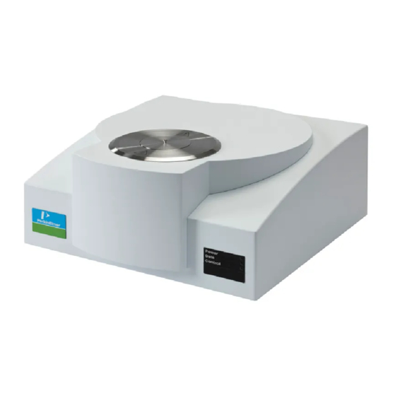
The STA 6000 is controlled by Pyris Software on the computer to which the analyzer is connected. The information it provides is essential to industries such as plastics and polymers;... - Page 57 STA 6000 Hardware . 57 For more information on the features of the STA 6000, see the topics below: Safety Precautions • • Sample Handling • Heating • Calibration Maintenance • Part Numbers • AS 8000 Autosampler •...
-
Page 58: Sample Handling
Solid materials can be sliced into small pieces with a razor or knife. If you are using the AS 8000 with the STA 6000, the sample size should be approximately 40 mg. Sample Pans The preferred sample pan is the self-centering, thin-walled, ceramic sample pan provided with the instrument. -
Page 59: Loading The Sample Into The Sta 6000
When necessary, this ring should be changed. Loading the Sample into the STA 6000 NOTE: Good quality data require uniform thermal contact between the pan and the support. Avoid spilling sample materials into the support. -
Page 60: Sta 6000 Maintenance
60 . STA 6000 Installation and Hardware GuideSTA 6000 Installation and Hardware Guide STA 6000 Maintenance The STA 6000 analyzer needs little routine maintenance other than giving it the proper treatment of a sensitive electromechanical device. Avoid contamination of the furnace by always using a system purge gas and, ideally, a sample purge gas. -
Page 61: Sta 6000 Part Numbers
Your order will be shipped promptly, usually within 24 hours. If you are located outside the U.S., call your local PerkinElmer sales office, or go on-line to www.perkinelmer.com Below is a list of the part numbers that are included with the STA 6000: Part No. Description... - Page 62 62 . STA 6000 Installation and Hardware GuideSTA 6000 Installation and Hardware Guide...
-
Page 63: As 8000 Autosampler
AS 8000 Autosampler... -
Page 64: As 8000 Autosampler
6000, STA 6000 and TGA 4000 when used in conjunction with the Pyris software Player feature. NOTE: If you have an STA 6000, then you will need firmware for Pyris version 9.1 or later to operate the AS 8000 autosampler. Select Programs > Pyris Software > Pyris User manuals >... - Page 65 AS 8000 Autosampler . 65 The light switch sensors by the furnace hole detect the presence of a sample pan or • furnace lid being placed in the furnace hole. If the autosampler is supposed to be removing a lid, for example, and the gripper fails to pick up the lid, it is detected by the sensors and an error message is displayed.
-
Page 66: Safety Precautions For The As 8000
The safety precautions to be followed when using the AS 8000 autosampler are the same as those for the parent instrument: STA 6000, DSC 4000, DSC 6000, or the TGA 4000. In addition, the following two precautions should be kept in mind: To rem ove the furnace lid(s) of the parent instrum ent, alw ays use tw eezers. -
Page 67: How The As 8000 Autosampler Works
The fingers are closed. The furnace lid (for the TGA 4000 and STA 6000) or lids (for the DSC 4000 or DSC 6000) are on the lid holders in the furnace access hole. The gripper device is instructed via a command in the Pyris software to begin a session. - Page 68 To remove the last sample from the furnace, set “Prepare Sample -Return Sample # #” as the last Play list step, where # # is the last sample loaded. A typical work cycle for the autosampler on a TGA 4000 or an STA 6000 and used with a play list is as follows: NOTE: Before the start of a play list, the gripper should be over the home position and there should be no sample pan in the furnace.
- Page 69 11. If there is another sample in the list, the work cycle, starting with step 1, begins again. Reduced Time Cycle A reduced time cycle is available for the STA 6000, TGA 4000, DSC 4000 and DSC 6000. This feature is accomplished by using either a Sample Group or by doing successive Load Sample commands without an explicit Return Sample.
-
Page 70: As 8000 Autosampler Gripper Alignment
70 . STA 6000 Installation and Hardware GuideSTA 6000 Installation and Hardware Guide AS 8000 Autosampler Gripper Alignment The autosampler is aligned at the factory. However, if you install a reference pan into your DSC instrument or change the sample thermocouple of your TGA instrument, change the sensor, or if the gripper does not grasp the sample pans correctly, you should perform a gripper alignment procedure. -
Page 71: As 8000 Sample Handling
10, 25, 30, and 50 µL. Sample Loading Before loading the sample into the crucibles for the TGA 4000 or STA 6000, you will have to tare the crucibles, that is, have the system weigh them so the weight of the crucible is not included in the data. - Page 72 72 . STA 6000 Installation and Hardware GuideSTA 6000 Installation and Hardware Guide When you click the OK button in the Advanced Tare Options dialog box, the Tare/Weigh System screen appears:...
- Page 73 AS 8000 Autosampler . 73 The Sample List will now display the tare weights of the crucibles: Once the empty crucibles are tared, remove each crucible and load the prepared sample into each one. Return the crucible to the correct position in the tray. Now the system can weigh all the samples before running the play list, or you can have each sample weighed at the beginning of its run.
-
Page 74: Running A Play List With The As 8000
There are many ways to use the play list with the autosampler. A quick way to create a play list for an STA 6000 or a TGA 4000 using the Sample Group feature is given below: –... - Page 75 AS 8000 Autosampler . 75 – Click OK and the Tare/Weigh System dialog box appears. The AS 8000 begins the procedure of taring the sample pans present on the sample trays. As it finds and tares each pan, it populates the Sample List and includes the tare weight for the sample pan in the Sample line.
- Page 76 76 . STA 6000 Installation and Hardware GuideSTA 6000 Installation and Hardware Guide – Remove the sample trays from the autosampler, or leave them in place, to load the crucibles. If you removed the trays, carefully return them to the autosampler and make sure that the two knobs on the bottom of each tray engage the holes in the autosampler plate.
- Page 77 AS 8000 Autosampler . 77 – Next you need to add some items to the Data Analysis List. If you have not entered a method for the Sample List, however, you cannot fill in the Data Analysis List. To enter a method, highlight the Sample List line. Type in the name of the method in the Method Name field or click the Browse button and find and select the method you want to use.
- Page 78 78 . STA 6000 Installation and Hardware GuideSTA 6000 Installation and Hardware Guide 9. Save the play list by selecting Save Player from the File menu. 10. Start playback of the play list by clicking the Start at Top button or the Start at Current Item button on the Player toolbar.
-
Page 79: Troubleshooting
AS 8000 Autosampler . 79 Troubleshooting When the AS 8000 autosampler malfunctions, in most cases it will generate an error message which is sent to the computer and is displayed in the Pyris software. The troubleshooting list below should be used if the AS 8000 malfunctions. To continue normal operation with the parent instrument, switch off the instrument and then switch it back on after 10 seconds. - Page 80 80 . STA 6000 Installation and Hardware GuideSTA 6000 Installation and Hardware Guide Error message ID Error Possible Corrective Cause Action ERR_GRP_WIRE_BROKEN Gripper wire is broken or Gripper wire is Replace gripper no AS 8000 mechanics broken assembly connected AS 8000...
- Page 81 AS 8000 Autosampler . 81 Error message ID Error Possible Corrective Cause Action ERR_FURN_NOT_EMPTY Furnace still contains a Failure picking Check if gripper sample while trying to sample out of fingers are bent. load a new one. This furnace Replace gripper error can be generated assembly only after loading at...
- Page 82 82 . STA 6000 Installation and Hardware GuideSTA 6000 Installation and Hardware Guide Error Messages from the STA 6000 Error message ID Error Possible Cause Corrective Action ERR_DUE_TO_AUTOSAMPLER AS 8000 entered Refer to the AS Refer to AS 8000 fatal error state.
-
Page 83: As 8000 Autosampler Maintenance
AS 8000 Autosampler . 83 AS 8000 Autosampler Maintenance The exterior surfaces of the AS 8000 may be cleaned with a soft cloth, dampened with a mild detergent and water solution. The bushings of the gripper fingers should also be kept clean. Use a Q-tip dampened with a mild detergent and water solution to carefully wipe them clean. - Page 84 84 . STA 6000 Installation and Hardware GuideSTA 6000 Installation and Hardware Guide...
Need help?
Do you have a question about the STA 6000 and is the answer not in the manual?
Questions and answers