Table of Contents
Advertisement
Advertisement
Table of Contents

Summary of Contents for IDEAL MSC-18K-X-236
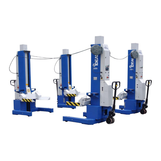
- Page 1 Mobile Column Lift Model Sets MSC-18K-X-236, MSC-18K-X-472 & MSC-18K-X-6108 Capacity 18,000lbs / Each Column Installation - Operation – Service Manual IMPORTANT!! READ MANUAL THOROUGHLY BEFORE INSTALLING, OPERATING, SERVICING OR MAINTAINING LIFT May 2019...
-
Page 2: Table Of Contents
INDEX PREFACE--------------------------------------------------------------------------- PAGE 2 PRODUCT IDENTIFICATION-------------------------------------------------- PAGE 2 OWNER / EMPLOYER OBLIGATIONS------------------------------------- PAGE 3 IMPORTANT SAFETY INSTRUCTIONS----------------------------------- PAGE 4 LOCATION------------------------------------------------------------------------- PAGE 7 GENERAL INFORMATION ---------------------------------------------------- PAGE 9 SET-UP / INSTALLATION ------------------------------------------------------ PAGE 10 SYSTEM TESTING BEFORE ACTUAL USE------------------------------ PAGE 15 LIFTING OPERATION----------------------------------------------------------- PAGE 20 MAINTENANCE INSTRUCTIONS ------------------------------------------- PAGE 21 SERVICE --------------------------------------------------------------------------- PAGE 22... -
Page 3: Owner / Employer Obligations
OWNER / EMPLOYER OBLIGATIONS 1. The Owner/Employer shall ensure that lift operators are qualified and that they are trained in the safe use and operation of the lift using the manufacturer’s operating instructions; ALI/SM10-1, ALI Lifting it Right safety manual; ALI/ST-10 ALI Safety Tips card; ANSI/ALI ALOIM-2008 (R2013), American National Standard for Automotive Lifts - Safety Requirements for Operation, Inspection and Maintenance;... -
Page 4: Important Safety Instructions
6. The Owner/Operator shall provide necessary lockout/tag out means for energy sources per ANSI Z244.1-1982 (R1993), Safety Requirements for the Lockout/Tag out of Energy Sources, before beginning any lift repairs and maintenance. 7. The Owner/Employer shall not modify the lift in any manner without the prior written consent of the manufacturer. - Page 5 9. Adequate ventilation should be provided when working on operating internal combustion engines. 10. Keep hair, loose clothing, fingers, and all parts of body away from moving parts. 11. To reduce the risk of electric shock, do not use on wet surfaces or expose to rain. 12.
- Page 6 24. Check and adjust if need the correct air pressure in all tires before lifting. Do not exceed tire load when raising vehicle. 25. DO NOT raise / lower only one side if a vehicle. 26. Lift only on same axle. Do not stagger between axles. 27.
-
Page 7: Location
For additional safety instructions regarding lifting, lift types, warning labels, preparing to lift, vehicle spotting, vehicle lifting, maintaining load stability, emergency procedures, vehicle lowering, lift limitations, lift maintenance, good shop practices, installation, operator training and owner/employer responsibilities, please refer to “Lifting It Right” (ALI/SM) and “Safety Tips” (ALI/ST) and vehicle lift points for service garage lifting SAE J2184. - Page 8 SAFETY DECALS These Decals Must Be Applied to Lift. REFERENCE: AUTOMOTIVE LIFT INSTITUTE, Inc. NOTE: SOME IMAGES IN THIS MANUAL ARE GENERIC AND MAY NOT RESEMBLE THE LIFT YOU HAVE PURCHASED. MSC-18K-X May 2019...
-
Page 9: General Information
1. GENERAL INFORMATION SPECIFICATIONS Models # MSC-18K-X-236, MSC-18K-X-472 & MSC-18K-X-6108 Capacity 18,000 lbs. / Each Column Pressure Relief Valve 2,030 psi Sealed Ex-Works Pump motor 4HP ( 3Kw, DC24V, Max 125 Amp ) / Each Column Battery charger power Input: 100-140VAC, 60Hz, Single Phase... -
Page 10: Set-Up / Installation
2. SET-UP / INSTALLATION Remark: Only move the lifting column with the forklift. Only raise the lifting column at the correct points. Damage to lifting column and /or injury to persons may occur if the lifting column is not moved in the correct manner. 2.1 PACKING LIST The complete lift is a set of either two (2), four (4) or six (6) mobile column lifting units and one (1) parts box, based on model type. - Page 11 It is the user’s responsibility to provide all wiring for electrical hook-up prior to installation and to insure that the electrical installation conforms to local building codes. Where required, it is the user’s responsibility to provide an electrical isolation switch located in close proximity to the lift that will enable emergency stop capability and isolate electrical power from the lift for any servicing requirements.
- Page 12 UNPACKING AND HANDLING THE LIFTING COLUMN Unpacking Procedure · Remove all plastic wrap and cardboard. Be careful not to cut into the lower hydraulic hoses and fittings or to scratch the paint or damage the safety decals. · Carefully open the parts box, avoid cutting the enclosed communication cables. ·...
- Page 13 To charge the battery, if necessary. A battery charger is built into each column. Plug the battery charger power supply cord into a 110 volt grounded electrical outlet. Charge each mobile column lifts using a separate electrical outlet. Best performance will be obtained by charging all mobile column batteries at the same time.
- Page 14 WARNING RISK OF EXPLOSIVE GASES WORKING IN THE VICINITY OF A LEAD ACID BATTERY IS DANGEROUS. BATTERIES CONTAIN SULFURIC ACID AND PRODUCE EXPLOSIVE GASES. A BATTERY EXPLOSION COULD RESULT IN LOSS OF EYESIGHT OR SERIOUS BURNS. FOR THIS REASON, IT IS OF UTMOST IMPORTANCE THAT YOU FOLLOW THE INSTRUCTIONS EACH TIME YOU USE THE CHARGER.
-
Page 15: System Testing Before Actual Use
System testing before actual use (Do not do any testing with a vehicle) Familiarize yourself with the electronic controls and warning lights by reviewing the functions of each item listed below. The Electronic Control Panels: The electronic control system of MSC-18K-X includes one master and either one, three or five slave control panels, based on the model type. - Page 16 Sub Control Panels - #2, #3, #4, #5, #6 Columns CONTROL PANEL DETAILS 1. EMERGENCY Button To stop movements (lifting or lowering) immediately. 2. POWER Switch Controls the power of the control panel or charging of the batteries. 3. ‘⇑ ’ ( UP ) Button Controls the lifting of the columns.
- Page 17 11. 12. 13. MODE Buttons To select between the functions: “WHEEL”, “AXLE” & “ALL” 14. BIAS Button To set the zero point of height in initialization. 15. START Button To start the running of the software. 16. SHIFT Button This button is for the running of the program. 17.
- Page 18 COLUMN POSITIONS & CONNECTIONS Depending on the model type, a full combination consists of either 2, 4 or 6 lifting columns. The position of the main column 1# should be located opposite of column 2# loading on the same axel of vehicle.
- Page 19 OPERATION TEST The mobile column lifts are designed in such a way as to offer maximum flexibility and convenience. A lifting system can consist of 4 lifting columns. The mobile column lifts are set-up as following: 1. Position the lifting columns as indicated in 3.3 (Fig. 3.3.) 2.
-
Page 20: Lifting Operation
Park: 1. Press and hold the ‘Park’ button, the carriage will go down until the safety lock is engaged. Mode ‘Wheel’ or ‘Axle’ test: 1. Press the button ‘Wheel’ or ‘Axle’ or ‘All’ to change mode. 2. In ‘Wheel’ mode, only that button pressed column will operate. 3. -
Page 21: Maintenance Instructions
Operation 5. Connect all communication cables as show in Fig. 3.3 6. Turn on all the battery switches on columns. Then turn on all the power switch with the master one in the last. 7. Depress the “UP” button and let columns rise approx. 6 inches. Release the “UP” button and inspect all of the columns to insure that the lifting arms are positioned properly. -
Page 22: Service
Monthly: · Test the emergency stop button on all columns. Columns should stop immediately. · Check the battery charging cables and cable ends. · Inspect communication cables and cable ends for wear or damage. · Check oil levels in hydraulic pump tank. Add oil on necessary. Annually: ·... - Page 23 Preparation Employees authorized to perform lockout shall ensure that the appropriate energy isolating device (circuit breaker, fuse, disconnect, etc.) is identified for the lift being locked out Other such devices for other equipment may be located in close proximity of the appropriate energy isolating device. If the identity of the device is in question, see the shop supervisor for resolution.
-
Page 24: System Diagnostic Messages
7. System Diagnostic Messages The mobile column lifts have self-diagnostic systems that may display a fault message on the LCD screen. Most fault messages indicate some sort of operator error and are designed so the user can correct the most common operation mistakes without employing a service technician. Listed below are the most common fault messages. -
Page 25: Emergency Lowering Procedure
8. Emergency - Manual Lowering Procedure WARNING!! THIS PROCEDURE IS RECOMMENDED TO BE PERFORMED BY A QUALIFED SERVICE PERSON AND/OR A FULLY TRAINED OPERATER Note: Before performing this procedure, make sure there are no obstructions that will affect lowering down. In case of an emergency or without power, please use the supplied magnet ring found in the parts box, to lower each column down manually. -
Page 26: Exploded Views & Parts Lists
EXPLODED VIEWS & PARTS LISTS Column Assembly Drawing #1 MSC-18K-X May 2019... - Page 27 Column Assembly Parts List ITEM Tux P/N M-Ref P/N DESCRIPTION MSC-18KX-01-001 DJ02-04000-000 Right Fork MSC-18KX-01-002 5102-12035-000 Bolt, M12 x 35mm MSC-18KX-01-003 DJ02-02003-000 Nylon Slider MSC-18KX-01-004 5202-00012-000 Self-Lock Nut, M12 MSC-18KX-01-005 DJ02-00011-000 MSC-18KX-01-006 5114-05014-000 Socket Screw, M5 x 14mm MSC-18KX-01-007 DJ02-02001-000 Roller MSC-18KX-01-008 DJ02-02005-000...
- Page 28 43-4 MSC-18KX-01-043.4 DJ02-11002-000 Small Roller MSC-18KX-01-044 DJ02-00018-000 Weight Bar MSC-18KX-01-045 5102-08020-000 Bolt, M8 x 20mm MSC-18KX-01-046 5302-00008-000 Flat Washer, D8 MSC-18KX-01-047 5901-00010-000 O-Ring, D10 x 2.4 MSC-18KX-01-048 DJ02-00004-000 Coil Support Board MSC-18KX-01-049 DJ02-00006-000 Electro-Magnet MSC-18KX-01-050 5102-05040-000 Bolt, M5 x 40mm MSC-18KX-01-051 DJ02-00031-000 Coil Fixing Board...
- Page 29 MSC-18KX-01-090 5102-14035-000 Socket Bolt, M14 x 35mm MSC-18KX-01-091 DJ02-00036-000 Washer MSC-18KX-01-092 DJ02-00035-000 Protecting Board MSC-18KX-01-093 DJ02-10100-000 Roller Holder MSC-18KX-01-094 5304-00025-000 Circlip, D25 MSC-18KX-01-095 DJ02-10102-002 Spacer MSC-18KX-01-096 DJ02-10002-001 Shaft MSC-18KX-01-097 DJ02-10001-000 Roller MSC-18KX-01-098 5906-00070-000 Dust Ring, D70 MSC-18KX-01-099 DJ02-05005-000 Guide Belt - #2 MSC-18KX-01-100 DJ02-05004-000 Guide Ring...
- Page 30 Control Panel Assembly Drawing #2 MSC-18K-X May 2019...
- Page 31 Control Panel Assembly Parts List ITEM Tux P/N M-Ref P/N DESCRIPTION MSC-18KX-02-001.1 DJ02-20002-000-Grn Operation Button, Green MSC-18KX-02-001.2 DJ02-20002-000-Blu Operation Button, Blue MSC-18KX-02-001.3 DJ02-20002-000-Blk Operation Button, Black MSC-18KX-02-002 DJ02-20003-000 Emergency Button, Red MSC-18KX-02-003 DJ02-20010-000 Screen, Main MSC-18KX-02-004 5110-00004-000 Screw, M4 x 12mm MSC-18KX-02-004.1 5203-00004-000 Spring Washer, D4...
- Page 32 Power Unit Assembly Drawing #3 MSC-18K-X May 2019...
- Page 33 Power Unit Assembly Parts List ITEM Tux P/N M-Ref P/N DESCRIPTION MSC-18KX-03-001 BZ22-05001-300 DC Motor, 24VDC, 3KW, 125A MSC-18KX-03-002 BZ01-04008-000 Close Nut, 9/16-18 UNF MSC-18KX-03-003 5901-00118-000 O-Ring, D11.8 x D1.8 MSC-18KX-03-004 BZ22-04001-F00 Valve Block MSC-18KX-03-005 BZ20-04002-000 Overflow Valve, 25Mpa MSC-18KX-03-005.1 5901-00160-000 O-Ring, D16 x D2 MSC-18KX-03-005.2...
-
Page 34: Limited Warranty
Limited One-Year Warranty: Tuxedo Distributors, LLC (iDEAL) offers a limited one-year warranty to the original purchaser of Lifts and Wheel Service equipment in the United States and Canada. Tuxedo will replace, without charge, any part found defective in materials or workmanship under normal use, for a period of one year after purchase.
Need help?
Do you have a question about the MSC-18K-X-236 and is the answer not in the manual?
Questions and answers
How do you rest height censor (encoder)