Table of Contents
Advertisement
Advertisement
Table of Contents

Summary of Contents for SKIPIO Salad Series
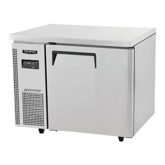
- Page 1 Commercial Refrigerator Service Manual Under Counter Table / Series Salad/ Dual Table Series SUR9-1 SUF9-1 SGR9-1 SHR9-1 SSR9-1 SUR12-2 SUF12-2 SGR12-2 SHR12-2 SSR12-2 SURF12-2 SUR15-2 SUF15-2 SGR15-2 SHR15-2 SSR15-2 SURF15-2 SUR18-3 SUF18-3 SGR18-3 SHR18-3 SSR18-3 SURF18-3...
-
Page 2: Table Of Contents
TABLE OF CONTENTS Section 1General Information ..................................... 4 1-1. How to use Power Cord ? ..................................4 1-2. How to disconnect the power cord? ..............................4 Section 2Installation Instructions ....................................5 2-1. How to remove packing instructions..............................5 2-2. Location Product ......................................6 Section 3 ............................................... - Page 3 3-3-1. Basic Operation ....................................22 3-4. PCB Function Manual ....................................23 3-4-1.How to set up manual defrost ..............................23 3-4-2. How to remove the manual defrosting ..........................23 3-4-3. How to set up the correction of inside temperature ....................24 3-4-4.
- Page 4 5-1-4.CONDENSER FAN MOTOR ................................37 5-1-5.EVAPORATOR FAN MOTOR ................................. 37 5-2. Filter Dryer ........................................38 5-3. Defrost Heater ......................................38 5-4. Thermal Fuse ........................................ 38 5-5. Capillary Tube Spec ....................................39 5-6. The cycle pressure of model starting (refrigerant weight) ..................... 39 5-7.
-
Page 5: Section 1General Information
Section 1General Information 1-1. How to use Power Cord? 1-1-1. Be sure not put more plug in the socket. Please use the dedicated outlet. -Overheated wire, which will cause fire or start malfunction 1-1-2. Wet hands off the power. - Life is in danger 1-2. -
Page 6: Section 2Installation Instructions
Section 2Installation Instructions 2-1. How to remove packing instructions Please set doors of products towards the same direction, tie the packing stick with ropes. Please cut the PE bag, then remove the packing box. Please remove all the packing parts around the products. Lift up the product, disassemble four screws, and then remove the packing base. -
Page 7: Location Product
2-2. Location Product Be sure to set the unit in door! To prevent damage, leakage! Be sure that the location be chosen has a strong enough floor to support total weight of the cabinet and any other contents. The uneven will make noise and shake! Be sure to avoid corrosive environment! It will shorten the life of the unit Be sure no object is on top of the product! -
Page 8: Section 3
Section 3 Product Instructions 3-1. EXPLODE VIEW 3-1-1. SUR 9-1 / SUF9-1/SGR9-1 Explode View Part Cord Part Name Part Cord Part Name KR81410400 MAIN PCB KU91100100 CABINET ASSY KR81410300 FRONT PCB KR92100302 UNIT BRACKET KR81410704 UNIT FRONT COVER KR81900104 UNIT SAID COVER KR89910100 BOTTOM HINGE(R)... -
Page 9: Shr 9-1 /Ssr9-1 Explode View
3-1-2. SHR 9-1 /SSR9-1 Explode View SHR9-1 SSR9-1... -
Page 10: Sur12-2/ Suf12-2/Sgr12-2Explode View
Part Cord Part Name Part Cord Part Name KR81410400 MAIN PCB BR9AB00100 CABINET ASSY KR81410300 FRONT PCB KR92100302 UNIT BRACKET KR81410704 UNIT FRONT COVER KR81900104 UNIT SAID COVER KR89910100 BOTTOM HINGE(R) KF24900105 CONDENSER ASSY 9 12 15 KR5AF00102 DOOR(R)_1500 KF84900105 CONDENSER ASSY 18 KR89910402 TOP HINGE(R)... -
Page 11: Shr12-2/Ssr12-2Explode View
Part Cord Part Name Part Cord Part Name KR81410400 MAIN PCB DK84400107 EVAP ASSY FRE KR81410300 FRONT PCB KR2FF00100 COUNTER TOP KR81410704 UNIT FRONT COVER KF85220305 EVAP FAN AIR GUIDE KR89940100 BOTTOM HINGE(L) KU21000100 CABINET ASSY 30229M0305 BOTTOM HINGE(L)GLASS KR92100301 UNIT BRACKET KR89910302 TOP HINGE(L)... - Page 12 SSR12-2 Part Cord Part Name Part Cord Part Name KR81410400 MAIN PCB BR2AB00100 CABINET ASSY KR81410300 FRONT PCB KR92100302 UNIT BRACKET KR81410704 UNIT FRONT COVER KR81900104 UNIT SAID COVER KR89910100 BOTTOM HINGE(R) KF24900105 CONDENSER ASSYREF KR2AF00102 DOOR(R)_1200 KF84900105 CONDENSER ASSYFRE KR89910402 TOP HINGE(R)...
-
Page 13: Surf12-2 Explode View
3-1-5. SURF12-2 Explode View Part Cord Part Name Part Cord Part Name KRF2500700 MAIN PCB KR2FF00100 COUNTER TOP KRF2500600 FRONT PCB KF85220305 EVAP FAN AIR GUIDE KR81410704 UNIT FRONT COVER KRF2000100 CABINET ASSY KR89940100 BOTTOM HINGE(L) KR92100301 UNIT BRACKET KR89910302 TOP HINGE(L)... -
Page 14: Sur15-2/ Suf15-2/Sgr15-2Explode View
3-1-6. SUR15-2/ SUF15-2/SGR15-2Explode View Part Cord Part Name Part Cord Part Name KR81410400 MAIN PCB DK84400107 EVAP ASSY FRE KR81410300 FRONT PCB KR2FF00100 COUNTER TOP KR81410704 UNIT FRONT COVER KF85220305 EVAP FAN AIR GUIDE KR89940100 BOTTOM HINGE(L) KU21000100 CABINET ASSY 30229M0305 BOTTOM HINGE(L)GLASS KR92100301... -
Page 15: Shr15-2/Ssr15-2Explode View
3-1-7. SHR15-2/SSR15-2Explode View SHR15-2 SSR15-2 Part Cord Part Name Part Cord Part Name KR81410400 MAIN PCB BR5AB00100 CABINET ASSY KR81410300 FRONT PCB KR92100302 UNIT BRACKET KR81410704 UNIT FRONT COVER KR81900104 UNIT SAID COVER KR89910100 BOTTOM HINGE(R) KF24900105 CONDENSER ASSYREF KR5AF00102 DOOR(R)_1500 KF84900105 CONDENSER ASSYFRE... -
Page 16: Surf15-2 Explode View
KR89910402 TOP HINGE(R) BR24200105 SUCTION PIPE(B) 12 15 U609000103 FAN COVER G2R5700200 COMP REF LX110 REF BR51H00100 EVA DUCT SHR G5R5700200 COMP FRE LX125 FRE BR51700108 EVA DUCT SSR BR84100100 FILTER DRYER CM25000101 EVA FAN MOTOR M729300102 DRAIN PAN BR2AD00103 EVAP-ASSY G8F5000200 CONDENSER FAN OTOR... -
Page 17: Sur18-3/ Suf18-3/Sgr18-3Explode View
KR5AF00202 DOOR(L)_1500 KF84900105 CONDENSER ASSY KR89910100 BOTTOM HINGE(R) KRF2600201 SUCTION PIPE(B) KR5AF00102 DOOR(R)_1500 NEK2150GK KR89910402 TOP HINGE(R) BR84100100 DRYER KRF5900100 EVA DRAIN GUIDE REF M729300102 DRAIN PAN KR91800203 EVA DRAIN GUIDE FRE G8F5000200 CONDENSER FAN MOTOR U609000103 FAN COVER REF KF82100208 UNIT BRACKET(A) KRF5200400... -
Page 18: Shr18-3/Ssr18-3Explode View
30229M0405 BOTTOM HINGE(R)GLASS COMP NEK2150GK FRE KR8AF00302 DOOR_1800(M) BR84100100 DRYER JG8AF00205 ASS'Y GLASS DOOR R M729300102 DRAIN PAN M722900106 DOOR_1800(R) G8F5000200 CONDENSER FAN MOTOR JG8AF00205 ASS'Y GLASS DOOR R KF82100208 UNIT BRACKET(A) KR89910402 TOP HINGE(R) K3F3200901 LEVEL FOOT&CASTER M722900108 TOP HINGE(R)GLASS KG81200100 SMPS KR91800201... - Page 19 SSR18-3 Part Cord Part Name Part Cord Part Name KR81410400 MAIN PCB BR8AB00100 CABINET ASSY KR81410300 FRONT PCB KR92100302 UNIT BRACKET KR81410704 UNIT FRONT COVER KR81900104 UNIT SAID COVER KR89910100 BOTTOM HINGE(R) KF24900105 CONDENSER ASSYREF KR8AF00102 DOOR(R)_1200 KF84900105 CONDENSER ASSYFRE KR89910402 TOP HINGE(R)...
-
Page 20: Surf18-3Explode View
3-1-11. SURF18-3Explode View Part Cord Part Name Part Cord Part Name KRF2500700 MAIN PCB KF85220305 EVAP FAN AIR GUIDE KRF2500600 FRONT PCB KRF8000100 CABINET ASSY KR81410704 UNIT FRONT COVER KR92100301 UNIT BRACKET KR89940100 BOTTOM HINGE(L) KR81900104 UNIT SAID COVER KR89910302 TOP HINGE(L)... -
Page 21: Wiring Diagram
3-2. Wiring Diagram 3-2-1 (SUR 9-1, SUR12-2, SUR15-2, SUR18-3 SGR 9-1, SGR12-2, SGR15-2, SGR18-3) 3-2-2. Wiring Diagram (SUF 9-1, SUF12-2, SUF15-2, SUF18-3) -
Page 22: Wiring Diagram (Shr 9-1, Shr12-2, Shr15-2, Shr18-3 Ssr 9-1, Ssr12-2, Ssr15-2, Ssr18-3)
3-2-3. Wiring Diagram (SHR 9-1, SHR12-2, SHR15-2, SHR18-3 SSR 9-1, SSR12-2, SSR15-2, SSR18-3) 3-2-4. Wiring Diagram ( SURF12-2, SURF15-2, SURF18-3) -
Page 23: Pcb Control Instruction
3-4. PCB Control Instruction 3-3-1. Basic Operation 1) Plug in and the Display panel will be lighted and make a beep sound. The compressor will begin to run. 2) The compressor is automatically cycled by the electronic controller (PCB). 3) The Defrost cycle is automatically controlled by the PCB. 4) Good Air Flow in refrigerator unit is critical. -
Page 24: Pcb Function Manual
3-4. PCB Function Manual 1. After PCB setting ,bar LED show the unit inside temperatue 1. By pushing the up/down button, you can set the inside temperature, temperature will be displayed. 3-4-1.How to set up manual defrost Cancel the frosting function of evaporator. STEP OPERATION DISPLAY... -
Page 25: How To Set Up The Correction Of Inside Temperature
3-4-3. How to set up the correction of inside temperature STEP OPERATION DISPLAY RESULT Step 1 Push the ▼ ▲ button Five seconds. Step 2 Push the ▼button twice time. Now is the setting value. Setting Step 3 Push the ▲ button When changed Reference Table1 value Table 1... -
Page 26: Change Model
Table 2 Display Description Display Description Memo "00" unchangeable " 50" 5.0℃ ↑ "-10" 1.0℃ ↓ " 40" 4.0℃ ↑ "-20" 2.0℃ ↓ " 30" 3.0℃ ↑ "-30" 3.0℃ ↓ " 20" 2.0℃ ↑ "-40" 4.0℃ ↓ " 10" 1.0℃ ↑ "-50"... -
Page 27: Change The Deforst Temperature
Table 4 Freezer Model Ref Model Changeable from 4 to 12 hours Changeable from 4 to 60 hours Default "6" Default "10" 3-4-7. Change the deforst temperature STEP OPERATION DISPLAY RESULT Step 1 Push the ▼ ▲ button Five seconds. Step 2 Push the ▼button twotime. -
Page 28: Control Eva Fan Motor
3-4-9. Control Eva fan motor STEP OPERATION DISPLAY RESULT Step 1 Push the ▼ ▲ button Five seconds. Step 2 Push the ▼button ninetime. Now is the setting value. Step 3 Push the ▼ button When changed Setting value Reference Table 7 Table 7 Setting value description... -
Page 29: Pcb Function Instructiondry -Type Model ( Ref / Fre)
- E²ROM cannot read and write Normal E²ROM ERROR running Refrigerator When the refrigerator defrost 40 minutes, it will Normal defrosting automatically stop. running ERROR - The COMP continuously run 30 minutes. Normal Cycle ERROR The temperature of D-SENSOR doesn’t reach 0℃ running(freeze 3-5. -
Page 30: Section 4Replacement Of Main Components
Section 4Replacement of Main Components 4-1. Mullion Heater replacement A. Unscrew the four screws from mullion. B. Disconnect the connectors from Mullion Heater top. C. Take apart mullion front cover from mullion. D. Pull out the heater from the inlet. -
Page 31: Cabinet Heater Replacement
E. Reinstall the new mullion heater, do reversed in order. F. Seal gaps with silicon after installation. 4-2. Cabinet Heater replacement A. Disassemble Unit Front Cover. B. Disconnect housing connector. - Page 32 C. Unscrew the top hinge. D. Lift the door and pull out the door. E. Insert the edge of “-“type screw driver into the gap between the frame and frame cover, take apart the frame. Pull out the heater from the inlet. F.
-
Page 33: Refrigeration Compartment Replacement
4-3. Refrigeration compartment replacement A. Disassemble Unit Front Cover. B. Unscrew unit Side Cover. C. Unscrew the comp base. D. ull out the condensing unit. Refrigeration compartment... -
Page 34: 4-4.Remove Counter Top
4-4.Remove Counter Top A. Unscrew the cabinet Reinforce. B. Unscrew the counter top bracket (Right). C. Unscrew the counter top bracket(Left). D. Cut the counter top out of cabinet as below. -
Page 35: 4-5.Remove Evap Motor
4-5.Remove Evap Motor A. Disassemble counter top and do as below. B. Unscrew Evap cover. Take apart Evap Motor Housing. -
Page 36: 4-6.Remove Evaporator
Unscrew Evap Motor Bracket. Remove Evap. 4-6.Remove Evaporator Disassemble Counter Top and Evap Motor, then do as below. Unscrew Air Guide, disconnect sensor connector, and take apart Air Guide. - Refrigerator... -
Page 37: Section 5Customer Support
- Freezer Section 5Customer Support 5-1. MAIN COMPONENTS 5-1-1.COMPRESSOR MODEL PART NAME PART NO. TYPE OF INPUT REFRIGERAN SUR/SGR9-1 / 12-2 / 15-2 LX110LAJM G2R5700200 1/4HP RSCR 220V 50Hz R-134a SUR / SGR18-3 LX125LAJM G5R5700200 1/3HP RSCR 220V 50Hz R-134a SUF9-1 / 12-2 / 15-2 LX125LAJM G5R5700200... -
Page 38: 5-1-3.Compressor Capacitor
5-1-3.COMPRESSOR CAPACITOR MODEL STARTING RUNNING MAKER NOTE SUR/SGR9-1 / 12-2 / 15-2 400V/5 ㎌ SUR / SGR18-3 400V/5 ㎌ SUF9-1 / 12-2 / 15-2 400V/5 ㎌ SUF18-3 330V/72~88чF SHR/SSR9-1 / 12-2 / 15-2 400V/5 ㎌ SHR/SSR18-3 400V/5 ㎌ SURF12-2 SURF15-2/SURF18-3 330V/72~88чF 400V/5 ㎌... -
Page 39: Filter Dryer
5-2. Filter Dryer MODEL PART NO. REFRIFERANT SPEC NOTE SUR/SGR9-1 / 12-2 / 15-2 SUR / SGR18-3 SUF9-1 / 12-2 / 15-2 BR84100101 R-134a C-052-5 SUF18-3 SHR/SSR9-1 / 12-2 / 15-2 SHR/SSR18-3 SURF12-2 SURF15-2/SURF18-3 5-3. Defrost Heater MODEL PART NO. SPEC NOTE SUF9-1... -
Page 40: Capillary Tube Spec
5-5. Capillary Tube Spec Model Suction Pipe A Suction Pipe B Tube I.D Length Tube I.D Length SUR9-1 SGR9-1 Ф2.4XФ1.2 600mm Ф2.4XФ1.2 2500mm SUR12-2 SGR12-2 Ф2.4XФ1.2 600mm Ф2.4XФ1.2 2500mm SUR15-2 SGR15-2 Ф2.4XФ1.2 600mm Ф2.4XФ1.2 2500mm SUR18-3 SGR18-3 Ф2.4XФ1.2 600mm Ф2.4XФ1.2 3000mm SUF9-1 Ф2.4XФ1.2... - Page 41 SHR12-2 LX110LAJM R134a 240gr SHR15-2 LX110LAJM R134a 240gr SHR18-3 LX125LAJM R134a 300gr SSR9-1 LX110LAJM R134a 240gr SSR12-2 LX110LAJM R134a 240gr SSR15-2 LX110LAJM R134a 240gr SSR18-3 LX125LAJM R134a 300gr SURF12-2 LX125LAJM R134a 290gr SURF15-2 NEK2150GK R404a 310gr SURF18-3 NEK2150GK R404a 320gr...
Need help?
Do you have a question about the Salad Series and is the answer not in the manual?
Questions and answers
I have the sgr18-3, it works completely fine until it does a defrost. The defrost is way too long and milk goes off inside. On defrost, it will take almost 2 hours to go to 20 degrees, even if I leave the doors open to speed up the process it doesn’t work.