
Related Manuals for Beny Sports Xer-Fit

Summary of Contents for Beny Sports Xer-Fit
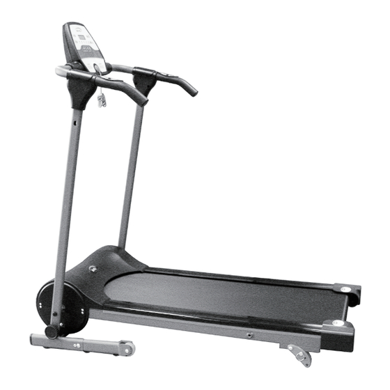
- Page 1 SERIAL NO. HY2761-UK Xer-Fit FOLDING MOTORISED TREADMILL Assembly & User Manual Please ensure that you read this manual carefully before attempting to assemble or use your new product and retain for future use...
-
Page 2: Table Of Contents
Contents Page Section General Information ..Before You Start ..Safety ..... 5 Exercise Information . -
Page 3: General Information
Failure from Monday to Friday to do so will result in any claim for replacement parts or Beny Sports Co. UK Ltd. repairs being refused. Unit 8, Riparian Way, The Crossings, Cross Hills, This guarantee, (both given and implied) applies to the West Yorkshire. -
Page 4: Before You Start
Before you Start Tools If required, most of our products are supplied with basic tools, which will enable you to successfully assemble your product. However, you may find it beneficial to have a soft-headed hammer and perhaps an adjustable spanner handy as this may help. Prepare the Work Area It is important that you assemble your product in a clean, clear, uncluttered area. -
Page 5: Safety
Safety Before you undertake any programme of exercise that will increase cardiovascular activity please be sure to consult with your doctor. Frequent strenuous exercise should be approved by your doctor and proper use of your product is essential. Please read this manual carefully before commencing assembly of your product or starting to exercise. - Page 6 Safety Safety-Treadmill Specific When using an electrical Treadmill, basic precautions should always be followed, including the following: Read all instructions before using the treadmill. DANGER – To reduce the risk of electric shock: Always unplug this Treadmill from the electrical outlet immediately after using and before cleaning and maintenance.
- Page 7 Exercising Information Warm Up A successful exercise programme consists Beginning of three parts, Warm Up, Aerobic Exercise and Cool Down. Never start a training How you begin to exercise will vary session without warming up. Never finish from person to person. If you have one without cooling down correctly.
-
Page 8: Exercise Information
Exercising Information Target Zone (con't) USERS UNCONDITIONED CONDITIONED TARGET ZONE - A TARGET ZONE - B (Years) (Beats per Minute) (Beats per Minute) 20-24 145 - 165 155 - 175 25-29 140 - 160 150 - 170 30-34 135 - 155 145 - 165 35-39 130 - 150... - Page 9 Exercising Information Shoulder Lift Rotate and lift your right shoulder up towards your ear for one count. Relax then repeat for the left shoulder. Repeat 3 - 4 times. Calf / Achilles Stretch Turn towards the wall and place both hands on it. Support yourself with one leg while the other is placed behind you with the sole flat on the floor.
-
Page 10: Assembly
Assembly Overview Drawing USING THE SAFETY KEY You will need to install the SAFETY KEY (4) in order to operate your product. This acts as an emergency STOP should you encounter any difficulties. SETTING UP THE SAFETY KEY With the product switched off, place the Safety Key (4) into the recess in the front of the Computer Console (1). - Page 11 Assembly ACCESSORY FITMENT LIST These are all the accessories you will need to comp lete the assembly of your product. The following accessories are supplied in a pack and should be checked before attempting assembly. Item 10 Item 13 Item 51 Item 12 Item 9 Qty 2...
- Page 12 Carefully unpack each component, checking against the parts list that you have all the necessary parts to complete the assembly of your product. Beny Sports Co. UK Ltd Please note that some of the parts may be pre-fitted to major Unit 8, Riparian Way,...
- Page 13 Assembly Assemble the Wheel Frame L/R (21) to the Upright Frame (16) using 2 x M8 x 35mm Allen Bolts (22), 2 x M8 Flat Washers (9) and 2 x M8 Nuts (15). Now fit 2 x M4 x 16mm Screws (62) as shown below.
- Page 14 Assembly Lift up and assemble the Handlebar (11) to the Base Frame Uprights (16) using 1 x M8 x 15mm Allen Bolt (10) and 1 x M8 Curved Washer (51) on each side. As shown below. CAUTION: Take care not to trap and wires, feeding any excess into the Upright Tube. As shown below.
- Page 15 Assembly Please remove the 1 x packing screw from the back of the Console (1) and discard. Carefully rotate the Console (1) on the Handlebar (11) ANTI-CLOCKWISE as shown and secure in place using 2 x M5 x 25mm Screws (13) and 2 x M5 Curved Washers (12).
- Page 16 Assembly Assemble the Monitor Frame Covers (59L/R) to the Upright Frame (16) using 6 x M4 x 16mm Self Tapping Screws (3). To change the incline of the treadmill: Your treadmill is fitted with 3 incline positions. You can change the incline position by removing the Locking Pins (57) and inserting them into one of the three holes in the Incline Feet (56L/R) making sure they are equal on both sides.
-
Page 17: User Instructions
User Instructions TO FOLD YOUR TREADMILL Remove the Locking Knob (50) from the Upright Frame lower hole. Lift the rear of the Main Frame and fold upwards until the hole in the Main Frame is in alignment with the Upper Hole of the Upright Frame and insert the Locking Knob (50) To lower the Treadmill, pull out the Locking Knob (50) from the Upright Frame. - Page 18 User Instructions Do not attempt to start this Treadmill while you are standing on the Running Belt. Stand on the Side Rails, hold the Handrails, then start the Treadmill at a low speed. Carefully step onto the Running Belt & when comfortable increase the speed to the desired level. Failure to observe this caution can lead to overloading of the Motor and Control Board which can cause premature component failure that is not covered under guarantee.
- Page 19 User Instructions GENERAL OPERATION: 1. Switch on the Treadmill – First at the Mains Power Supply; then at the Power Switch (34); then place the Safety Key (4) in its position on the front of the Computer. 2. Press Start to enter Standby Mode. 3.
- Page 20 User Instructions PROGRAMME CHART Stage Prog ERROR SIGNALS / TROUBLESHOOTING Should your Treadmill fail to operate, please check the Console Display for any of the following Error Signals Er 1: The Console Display panel is not receiving a signal from the Motor or Control Board Er 3: Over voltage;...
-
Page 21: Lubricating The Running Belt
User Instructions ADJUSTING THE RUNNING BELT TRACKING If the Running Belt tends to move off central during operation, step off the belt and stop the Treadmill. Start the Treadmill in Manual Programme Mode and adjust the speed to 3mph. Take the 5mm Allen Wrench and adjust the Rear Roller Location Bolts, which are accessible through the Rear Frame Caps. If the belt is moving towards the RIGHT side of the Treadmill Running Board, turn the RIGHT Rear Roller Location Bolt 1/4 turn CLOCKWISE and let the Running Belt find its new position. - Page 22 Assembly Page 22...
-
Page 23: Parts List
Assembly PARTS LIST PART No. DESCRIPTION Front Roller ..... . Upper Console Cover ....M8 x 55mm Allen Bolt . -
Page 24: Customer Support
Beny Sports Co. UK Ltd. Unit 8, Riparian Way, The Crossings, Cross Hills, West Yorkshire BD20 7BW CUSTOMER SUPPORT is open from 9.00am to 5.00pm from Monday to Friday Tel: 01535 637711 Fax: 01535 637722 E-mail: support@benysports.co.uk Website: www.benysports.co.uk Copyright BSCL 2017...
Need help?
Do you have a question about the Xer-Fit and is the answer not in the manual?
Questions and answers