Table of Contents

Summary of Contents for Kimpex 058121
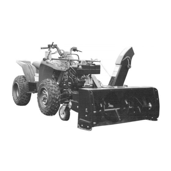
- Page 1 OWNER’S MANUAL Model Number 058121 700310-6 Kimpex Two Stage 48" Snowblower ALL TERRAIN VEHICLES * ASSEMBLY * REPAIR PARTS * OPERATION * MAINTENANCE CAUTION: READ & FOLLOW ALL SAFETY RULES & INSTRUCTIONS BEFORE OPERATING YOUR EQUIPMENT 104485 G-09...
- Page 2 NOTE: All warranty work must be performed by an authorized dealer using original (manufacturer) replacement parts. Note: KIMPEX reserves the right to change or improve the design of any part or accessory without assuming any obligation to modify any product previously manufactured. Instructions for Obtaining Warranty Services: Contact dealer where equipment was purchased or any other KIMPEX Service Dealer to arrange service at their dealership.
-
Page 3: Table Of Contents
TABLE OF CONTENTS PAGE INTRODUCTION ..............................SAFETY PRECAUTIONS ............................SAFETY DECALS ..............................ASSEMBLY Step 1: Snowblower Preparation ......................Step 2: Subframe Preparation ......................... Step 3: Engine Installation ........................Step 4: Installation on the vehicle ......................OPERATION Operating the Snowblower ........................Controls .............................. -
Page 4: Introduction
INTRODUCTION TO THE PURCHASER This new attachment was carefully designed to give years of dependable service. This manual has been provided to assist in the safe operation and servicing of your attachment. NOTE: All photographs and illustrations in the manual may not necessarily depict the actual models or attachment, but are intended for reference only and are based on the latest product information available at the time of publication. -
Page 5: Safety Precautions
SAFETY PRECAUTIONS Careful operation is your best insurance against an accident. Read this section carefully before operating the vehicle. and snowblower. This snowblower is capable of amputating hands and feet and throwing objects. Failure to observe the following safety instructions could result in serious injury. All operators, no matter how experienced they may be, should read this and other manuals related to the vehicle and attachments before operating. - Page 6 SAFETY PRECAUTIONS 16.Use only accessories approved 4. If the unit should start to vibrate abnormally, stop the manufacturer of the snowblower (such as wheel engine (motor) and check immediately for the cause. chains, and the like). Vibration is generally a warning of trouble. 17.Never operate the snowblower without good 5.
-
Page 7: Safety Decals
SAFETY DECALS REPLACE IF DECALS ARE DAMAGED SEE PARTS BREAKDOWN FOR DECAL LOCATION Decal # 102125 Decal # 102126 Decal # 102128 Decal # 102127 Decal # 102553 Decal # 102671... - Page 8 ASSEMBLY IMPORTANT: TORQUE ALL BOLTS ACCORDING TO TORQUE SPECIFICATION TABLE (SEE TABLE CONTENTS) WHEN STATED: TIGHTEN FIRMLY. REFER PARTS BREAKDOWN SECTION FOR PART IDENTIFICATION. STEP 1 SNOWBLOWER PREPARATION: Place snowblower face down. Place snowblower face down Install the hitch (item 1) with three 7/16 x 1 1/4" bolts (item 2), lock washers, nylon insert locknuts and a 7/16 x 1 1/4"...
- Page 9 ASSEMBLY Grease both ends of the rotation worm (item 1). Insert the short rotation bushing (item 2) and the long rotation bushing (item 3) as shown. Insert bushings on rotation worm Insert the rotation worm with the short bushing in the sleeve (item 1).
- Page 10 ASSEMBLY Install the hand guard (item 1) as shown. Secure in place with two 1/4 x 3/4" bolts (item 2) the flatwashers and flange nuts inside. Tighten the bolts firmly. Install hand guard...
- Page 11 ASSEMBLY STEP 2 SUBFRAME PREPARATION: Install the two caster wheels (item 1) to the wheel support (item 2) as shown. NOTE: If your vehicle is equipped with cat tracks, do not install the chains now. Install the two 3/16 x 32" chains (item 3) to the top of the plate of the wheel support with a 3/8 x 1"...
- Page 12 ASSEMBLY Install the subframe extension (item 2) to the subframe (item 1) using eight 3/8 x 3/4” hex bolts (item 3) and nylon nuts. Tighten firmly. NOTE: This subframe extension is adjustable in order to install cat tracks on the vehicle. Adjust to the appropriate length to your vehicle.
- Page 13 ASSEMBLY STEP 3 ENGINE INSTALLATION: NOTE: THE RIGHT INSTALLATION OF THE ENGINE IS CRUCIAL TO THE GOOD WORKING ORDER OF THE SNOWBLOWER. NOTE: Figures 1 and 2 show an engine that is not well positioned. Figure 2 Figure 1 Engine not in right position Engine not in right position IMPORTANT: We recommend using a 13 H.P.
- Page 14 ASSEMBLY INSTALLATION OTHER BRANDS ENGINES: Place the engine on a table. Measure the height (item B) from the middle of the crank shaft to the table. Use one of the two shims (3/4" or 1") if required, to attain the height of 5.25". If more or less height is needed, use a couple of flat washers.
- Page 15 Install the belts on the snowblower pulleys (items 5-6- Make sure that each strand of the belts are inside the pins that are used as belt guides (item 4). Verify the adjustment. The distance (item B) between the cable end (item 3) and the cable support should be 1/4’’...
- Page 16 ASSEMBLY Adjust the idler pulley as follows: After installing the belts, you may run the engine without the belt guard but only for the time needed to verify the belt alignment and only under strict supervision. Do not approach (you or anyone else) the moving parts.
- Page 17 ASSEMBLY STEP 4 INSTALLATION ON THE VEHICULE: Install the optional quick hitch mounting brackets (item 1) under the vehicle. Refer to the Mounting Bracket Chart to identify the proper bracket model for your vehicle. (see table of contents). Follow the mounting instructions supplied with the mounting bracket kit.
- Page 18 ASSEMBLY LIFT THE SNOWBLOWER USING THE A.T.V.’S WINCH: NOTE: Optional kit #700269 Lift connection kit (items 1 & 2) must be used. This kit will double the winch’s lifting and braking capacity and reduces the lifting speed by 50%. This will prevent damage to the snowblower’s engine.
-
Page 19: Controls
ASSEMBLY NOTE: To install the clutch controls and the rotation arm support on a vehicle which has a plastic rack (item 1), you must purchase the optional kit "Control support" (item 2). Control support Install the handle support (item 3) with the support bracket (item 2) using the 1/4 x 3/4"... - Page 20 ASSEMBLY Install the clutch support (item 4) by loosening the knob (item 1) and slide the front slot between the bolt head (item 2) and the support. Slide the back slot between the bolt head (item 3) and the support. Secure with the knob (item 1).
-
Page 21: Removing Snow
OPERATION OPERATING THE SNOWBLOWER WARNING a) Make sure the snowblower is clear of snow before engaging the clutch. Read the vehicle's owner’s manual carefully. Be b) Make sure that the auger and impeller operate thoroughly familiar with the controls & proper freely. -
Page 22: Adjustments
MAINTENANCE CUTTING EDGE MAINTENANCE WARNING Verify from time to time the wearing on the cutting TO PREVENT INJURIES: edge to make sure you do not wear out the base of Stop the snowblower motor. the snowblower’s chassis. This cutting edge is Apply parking brakes. -
Page 23: Belt Replacement & Adjustments
BELT REPLACEMENT & ADJUSTMENTS To adjust the cable, disengage the clutch arm. BELT REPLACEMENT: Loosen the two nuts (item 1). Adjust to obtain the right tension. The distance (item B) between the cable For belt part numbers, refer to parts breakdown support and the cable end (item 3) should be section for parts identification. -
Page 24: Troubleshooting
TROUBLESHOOTING PROBLEM POSSIBLE CAUSES CORRECTIVE ACTION Snowblower is noisy. New chain and new sprocket. Lubricate the roller chain. NOTE: Please note this NOTE: When snowblower is new it is snowblower may appear to be louder, the noise will decrease over noisy. - Page 25 TROUBLESHOOTING PROBLEM POSSIBLE CAUSES CORRECTIVE ACTION The chute plugs easily. Snowblower engine is turning too Always have engine at full R.P.M. slowly. when using the snowblower. Advancing too quickly with vehicule. Reduce speed. Allow snowblower to ingest snow at its own speed. Snowblower digs into ground.
-
Page 26: Mounting Bracket Chart
MOUNTING BRACKET CHART TABLEAU DES SUPPORTS DE MONTAGE BRAND MODEL QUICK HITCH BRACKET 700 EFI 2006-07 073040 650 4x4 V2 MRP 2005-06 073063 650 4x4 V2/LE 2005-06 073063 650 4X4 H1 2006 073040 650 4x4 H1 2005 073063 650I 4x4 Auto LE/MPR 2004 073040 500 4x4 /LE/MPR... - Page 27 MOUNTING BRACKET CHART TABLEAU DES SUPPORTS DE MONTAGE BRAND MODEL QUICK HITCH BRACKET KVF 750i Brute Force 2005-06 073364 KAWASAKI KVF 700 Prairie/HDW 4x4 2004-06 073341 KVF 650 Brute Force 2005-06 073361 KVF 650i Brute Force 2006 073364 KVF 650 2002-03 073397 KVF 400 4x4...
- Page 28 PARTS BREAKDOWN / NOMENCLATURE DES PIÈCES ROTATION SYSTEM WITH CHUTE SYSTÈME DE ROTATION AVEC GOULOTTE...
- Page 29 PARTS LIST / LISTE DES PIÈCES Ref. English description Description française Qty. Part # Kimpex # Réf. Qté. Pièce # Chute Goulotte 102058 088844 Knob Bouton 102020 088910 Nylon flat washer 11/32" Rondelle plate de nylon 11/32" 102009 Nylon flat washer 7/16"...
-
Page 30: Manual Clutch Mechanism
PARTS BREAKDOWN / NOMENCLATURE DES PIÈCES MANUAL CLUTCH MECHANISM / MÉCANISME D’EMBRAYAGE MANUEL... - Page 31 PARTS LIST / LISTE DES PIÈCES Ref. Qty. Part # Kimpex # English description Description française Réf. Qté. Pièce # 088405-1 Clutch support Support d'embrayage 104367 Clutch holder Fixation d'embrayage 104368 088912-1 088880 Rubber Caoutchouc 102545 Carriage bolt 5/16" n.c. x 1 3/4"...
-
Page 32: Subframe
PARTS BREAKDOWN / NOMENCLATURE DES PIÈCES SUBFRAME ASSEMBLY/ SOUS-CHÂSSIS ASSEMBLÉ... - Page 33 PARTS LIST / LISTE DES PIÈCES Ref. English description Description française Qty. Part # Kimpex # Réf. Qté. Pièce # Pivot support Support de pivot 102888 088864 Attaching flat bar Fer plat d'attache 102340 088845 Hex. bolt 7/16" n.c. x 1 1/4"...
-
Page 34: Snowblower
PARTS BREAKDOWN / NOMENCLATURE DES PIÈCES SNOWBLOWER / SOUFFLEUSE... - Page 35 PARTS LIST / LISTE DES PIÈCES Ref. English description Description française Qty. Part # Kimpex# Réf. Qté. Pièce # Frame 48" Châssis 48" 103339 088861 Gear box Boîte d'engrenage 102029 088874 Hex. bolt 3/8" n.c. x 4" Boulon hex. 3/8" n.c. x 4"...
- Page 36 PARTS LIST / LISTE DES PIÈCES Ref. English description Description française Qty. Part # Kimpex # Réf. Qté. Pièce # Pulley 2.5 ø with set screw Poulie 2.5 ø a/vis à pression 102330 088812 Pair of V-Belts, Raw Edge Paire de courroies en V, Raw Edge 103745 Hex.
-
Page 37: Torque Specification Table
TORQUE SPECIFICATION TABLE GENERAL TORQUE SPECIFICATION TABLE USE THE FOLLOWING TORQUES WHEN SPECIAL TORQUES ARE NOT GIVEN NOTE: These values apply to fasteners as received from supplier, dry or when lubricated with normal oil. They do not apply if special graphited or moly disulphide greases or other extreme pressure lubricants are used. This applies to both UNF and UNC threads. - Page 38 OPTIONS & ACCESSORIES (058275) #700269 (088936) #700301 (058274) #700261 LIFT CONNECTION KIT DRIFT EXTENSION KIT FOR 48" SNOW DRIFT CUTTER Doubles the winch’s lift and brake Increase snow intake. Slices through high snow drifts to facilitate and capacity. Prevents snow from getting in the engine. increase snow intake.
Need help?
Do you have a question about the 058121 and is the answer not in the manual?
Questions and answers